
Perfect Power Smt-6 Wiring Diagrams Guide


Senior Member
Joined: Dec 2005
Posts: 458
Likes: 0
From: York. About 2hrs from Philly and 4 hours from Pittsburgh
Just installed an smt 6 with a 99 tib. For everyone with a 97-99 car the ecu wire colors for the basic setup should be as follows:
Pin 55- black
Pin58- black w/ white stripe
pin 73- white
pin 41- white w/ yellow stripe
pin 47- white
Pin 55- black
Pin58- black w/ white stripe
pin 73- white
pin 41- white w/ yellow stripe
pin 47- white
Thread Starter
http://www.hyundaiaftermarket.org/images/vendor1.png

Joined: Mar 2006
Posts: 2,178
Likes: 0
From: Vancouver, BC, Canada
Vehicle: 01 Tiburon
UPDATE:
Thanks to nate704...
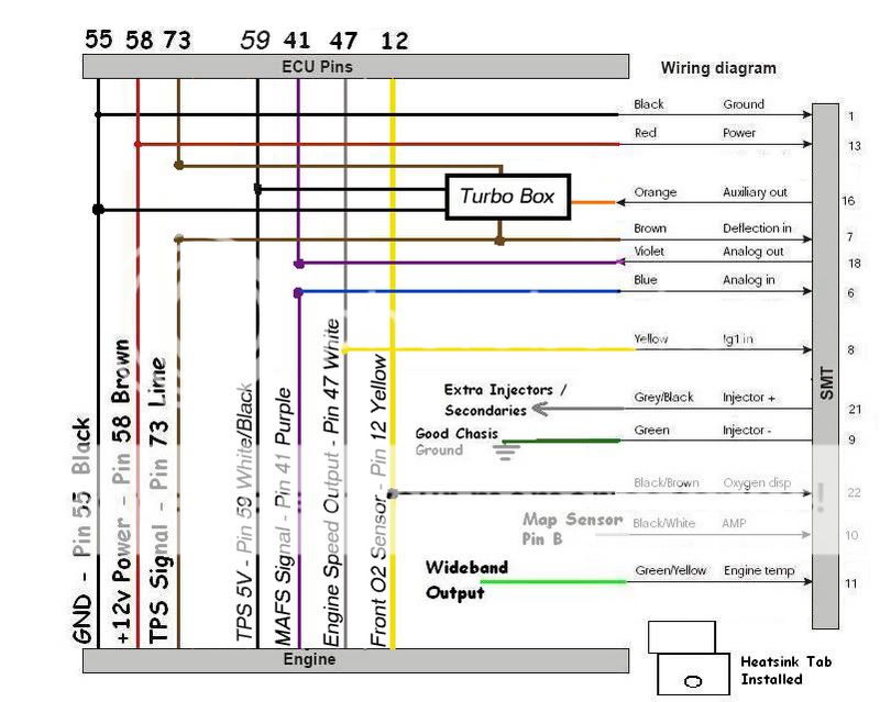
This is how denis' turbo box version 2 is connected! This wiring diagram also shows the secondary injectors' connections
Thanks to nate704...
This is how denis' turbo box version 2 is connected! This wiring diagram also shows the secondary injectors' connections


Thread Starter
http://www.hyundaiaftermarket.org/images/vendor1.png
Joined: Mar 2006
Posts: 2,178
Likes: 0
From: Vancouver, BC, Canada
Vehicle: 01 Tiburon
^^^
NYelantraGUy,
The ECM pin outs for your 02 Elantra is different from the RD's. Here is something that can help you out. You might need to spend some time on the drawing board devising a wiring diagram if one is not available for your vehicle.
01-02 Elantra ECM Pinout
1) ground 2.0B
2) ground 2.0B
3) battery voltage 2.0L
4) ignition coil 1 control 0.5G (cyl 1, 4)
5) ignition coil 2 control 0.5Y (cyl 2, 3)
6) low voltage tcm 0.3Br
7) high voltage tcm 0.3W
8) O2 sensor up heating 0.5P
9) O2 sensor down heating 0.5P
10) kns sensor signal 0.5Br
11)
12)
13)
14) battery voltage 0.5W
15)
16)
17) wheel speed input 0.5O (right front wheel sensor w/out abs)
18) wheel speed input 0.5G (right front wheel sensor w/out abs)
19)
20)
21) battery voltage 0.5W
22) on/start input 0.5R
23) injector 4 control 0.5O
24) injector 1 control 0.5L
25)
26) cpv control 0.5Y/O
27) cps ground 0.5L/B
28)
29) cps signal 0.5G
30) cps & kns sensor ground 0.5Gr
31) ect input 0.5G/B
32) tps signal 0.5L/B
33) ftp signal 0.5G/O
34) ftp ground 0.5L/B
35)
36)
37)
38) tps ground 0.5R/B
39) vehicle speed input 0.3Gr/O (with abs)
40)
41)
42) O2 sensor down signal 0.5G
43) O2 sensor up signal 0.5G
44) sensor power 5v 0.5R (map, ftp)
45) tps power 0.5L
46)
47) immo signal 0.5L/B (not used in U.S. and not availible on 01 model)
48) map sensor ground 0.5G
49)
50) a/c signal input 0.5Y
51) cooling signal input 0.5Br/O
52)
53)
54)
55) ground 0.5B
56) iat signal 0.5Gr(map)
57)
58) a/c switch "on" input 0.3Y/B
59) sensor ground 0.5B (O2 sensors and ect sensor)
60) map signal 0.5G
61) injector 3 control 0.5L/B
62) injector 2 control 0.5R/B
63)
64) fan relay control high 0.5Gr
65) fan relay control low 0.5Y/O
66) engine rpm signal 0.5L (cluster)
67) engine control relay control 0.5O
68) a/c relay control 0.5O
69) fuel pump relay control 0.5R/B
70) mil indicator control 0.3Br/O (cel)
71) immo ground 0.5B (not used in U.S. and not availible on 01 model)
72) cps sensor signal 0.5R/B
73)
74)
75) consumption 0.5L/O (micro controller in cluster)
76)
77) k-line 0.5G/B (dlc, tcm)
78) isa opening 0.5Gr
79) ccv control 0.5L/B
80) isa closing 0.5G
81)
Senior Member
Joined: Mar 2006
Posts: 4,135
Likes: 0
From: NAS Patuxent River, MD
Vehicle: 2004 Volkswagen Jetta GLI
ok im going to cuba for a year in Jan and i have been putting together my turbo project and i got the smt 6 and turbo box from denis...i will be using the duel rail kit also...and i want to get as much down that i can do without putting on turbo...so here is my question...
Can i hook up the SMT 6/turbo box as per that lastest diagram that Nate704 produced...but without the duel rail kit?
Can i hook up the SMT 6/turbo box as per that lastest diagram that Nate704 produced...but without the duel rail kit?

