
My Head Has Holes In It. They Need A Port And Polish!

Senior Member

Joined: Apr 2008
Posts: 2,087
Likes: 0
From: Western PA
Vehicle: 2001 Tiburon
Glad to see this thread is not dead. I cant wait till have an area where i can work on this stuff without freezing my but off outside.
Hey Caj, you going to run for march COTM again? hahh
Hey Caj, you going to run for march COTM again? hahh
Thread Starter
Super Moderator

Joined: Sep 2001
Posts: 10,795
Likes: 5
From: Pflugerville, TX
Vehicle: 2000 Elantra
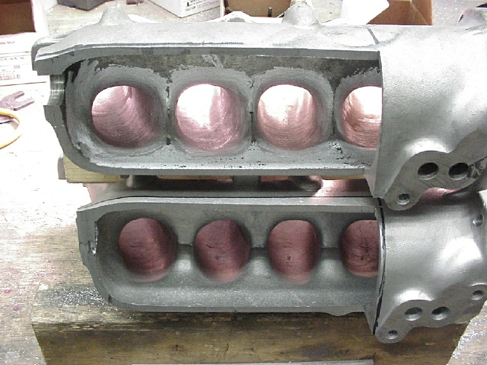
It's radii, and I'm not sure. The port match to which I refer is just that, matching the openings. Leave the opening in the head about 0.070- 0.080" larger and the intake air charge will have a harder time flowing backwards (anti-reversion step). The only way I can see getting into the actual runners is opening the surge tank, working it all over, then welding the surge tank back on. This would likely be the only type of IM P&P that would yield any meaningful gains, and that only by removing all the crap & flash that Hyundai leaves in the tank & runners. This is the procedure the Endyn uses when they do a number on a cast IM, by the way*. The runners are already a pretty good size (diameter) for this size of engine, and if you really want them bigger you're going to have to cut the tank anyhow so there it is. I'm not entirely sure it is worth the effort for my n/a driver, but then, look at this whole thread! laugh.gif
Dash it all, now you've got me wanting to open up my spare IM. Dangit. That's another couple of months I'll be without the P&P'd head on my car now!
*This is a Skunk2 cast aluminum manifold they did a P&P on as part of a high-power 2.0L Honda build up. It lost 2lbs. of aluminum. THAT is an IM P&P job. Grinding the flash out of the last 5" of each runner is not even in the same ballpark. If I didn't go for this level of effort, I would leave it at a quick port match and MAYBE knock off a couple of the worse pieces of flash.
"On the intake side, we’re using one of our killer Skunk2 manifolds. We recently flowed the head being used on this project with our single throttle body intake verses a number of different individual throttle body set-ups and the Edelbrock manifold, and we found that our manifold kicked all of their respective asses at every valve lift. We also noted that there was less pressure differential between measuring points with our manifold, translating to better velocity and hopefully a nicer torque curve. Once again, my trusty 64mm throttle body that Russ Collins reworked back in 1997 is being used with this manifold. I’m not going into detail about the manifold’s mods, but there are some pictures of it elsewhere in the article. It weighs 2.3 lbs less than it did when it was stock, if that tells you anything, and we also had to coat the bottom of the plenum and runners with a carbon-filled epoxy to prevent them from sucking shut if the throttle was suddenly closed at high rpm. Sounds scary, right?"
Thread Starter
Super Moderator
Joined: Sep 2001
Posts: 10,795
Likes: 5
From: Pflugerville, TX
Vehicle: 2000 Elantra
Chalk up another 3 hours on this head. The deshrouding of all the exhaust valves is finally done. No photos because it looks the same as it did before, except there's more red magic marker all over the exhaust side of all 4 chambers; I was doing a final check to make sure the intake valve I am using as a gauge cleared the walls all the way down. Now it does and I'm going to bed.
P.S. if this car doesn't go like stink when I am finally done I will be disappointed. As long as I can keep the compression at least as high as stock and get a good seal on both sides of all the valves (oil & air) it should be a real runner. There seems like no way you can fix as many ugly spots as Hyundai left in the air flow path and NOT have smoother running and higher VE.
P.S. if this car doesn't go like stink when I am finally done I will be disappointed. As long as I can keep the compression at least as high as stock and get a good seal on both sides of all the valves (oil & air) it should be a real runner. There seems like no way you can fix as many ugly spots as Hyundai left in the air flow path and NOT have smoother running and higher VE.
Thread Starter
Super Moderator
Joined: Sep 2001
Posts: 10,795
Likes: 5
From: Pflugerville, TX
Vehicle: 2000 Elantra
There's another 2 to 3 hours spent. The more time I pour into this head, the more I think this thread belongs in extreme mods, vs. engine & transmission!
Anywho, the extension on my rotary tool does indeed enable me to reach all the way to the corner of the ports, and I went to town on the exhaust side tonight. I removed some flash that I didn't even know was there until the sanding drum hit it. Then it sticks out like a sore thumb, and I grind it off. I got close to done with the shape of the sides of the ports, and left the floor and roof alone on all but one port. . . the one on the left, in these pictures.
Features to note:
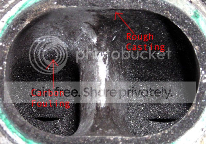
Carbon fouling was covering a big dip in the casting. The majority of the surfaces are fairly smooth, but then you also find several little ugly spots. In the runner on the right you can't see them because they're covered. On the left, they have been removed. All the way back to the top of the "carbon fouling" arrow. That is where a line of solid fouling starts that boogered up my sandpaper and it will have to be removed with a metal tool. The machinist at Performance chuckled and bade me "good luck" when I asked how to remove this stuff. It looks like it's going to have to just be the hard way and that's all there is to it.
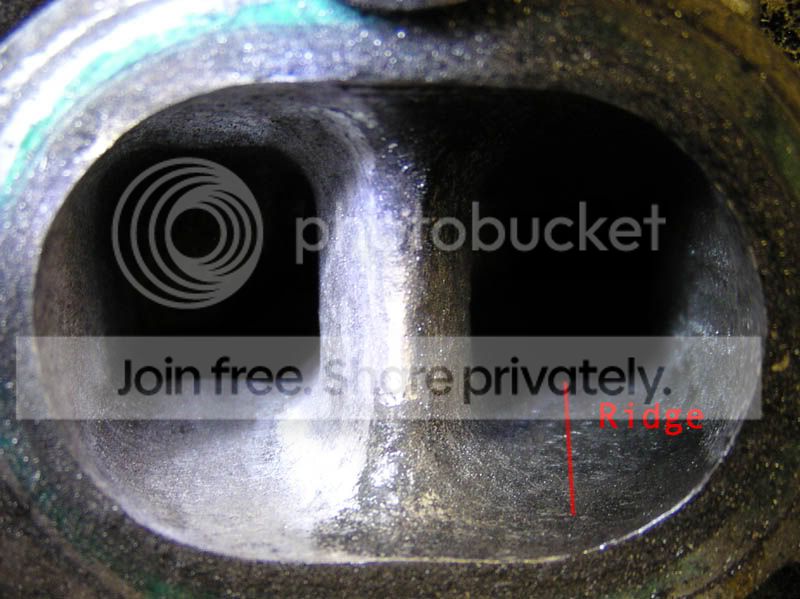
Not only is the short-side radius of the exhaust port entirely too sharp a bend, it also incorporates a hump right in the middle further displacing flow to the slower side of the port. The hump extends almost the entire length of the port as a ridge that I am smoothing and considering deleting altogether.
***
bonus/thank you Jesus: the inside corners are approximately the same diameter as a small Dremel sanding drum, which makes removing the roughness and flash MUCH much easier. cool.gif
Anywho, the extension on my rotary tool does indeed enable me to reach all the way to the corner of the ports, and I went to town on the exhaust side tonight. I removed some flash that I didn't even know was there until the sanding drum hit it. Then it sticks out like a sore thumb, and I grind it off. I got close to done with the shape of the sides of the ports, and left the floor and roof alone on all but one port. . . the one on the left, in these pictures.
Features to note:
Carbon fouling was covering a big dip in the casting. The majority of the surfaces are fairly smooth, but then you also find several little ugly spots. In the runner on the right you can't see them because they're covered. On the left, they have been removed. All the way back to the top of the "carbon fouling" arrow. That is where a line of solid fouling starts that boogered up my sandpaper and it will have to be removed with a metal tool. The machinist at Performance chuckled and bade me "good luck" when I asked how to remove this stuff. It looks like it's going to have to just be the hard way and that's all there is to it.
Not only is the short-side radius of the exhaust port entirely too sharp a bend, it also incorporates a hump right in the middle further displacing flow to the slower side of the port. The hump extends almost the entire length of the port as a ridge that I am smoothing and considering deleting altogether.
***
bonus/thank you Jesus: the inside corners are approximately the same diameter as a small Dremel sanding drum, which makes removing the roughness and flash MUCH much easier. cool.gif
Thread Starter
Super Moderator
Joined: Sep 2001
Posts: 10,795
Likes: 5
From: Pflugerville, TX
Vehicle: 2000 Elantra
Okay it's time for another update with something worth looking at. I cleaned up enough of the carbon gunk around one pair of exhaust ports to take a picture clear enough to publish. When the carbon is covering everything, trust me, it's nothing worth looking at. It's all solid black and you can hardly even cast a shadow, let alone make out the shape of anything. I used a long, thin stainless rod, the end of which I ground to something like a flat-headed screwdriver to chip/scrape the solid carbon out of there. I wrapped the shank of my field-expedient tool in vinyl electrical tape to protect the head, especially the valve seats. Anyhow, it was a bit of physical labor, combined with frustration at not being able to see/illuminate and work at the same time. It helped that I got a new, more-powerful light for Christmas (and that's where all the yellow/green in the photographs came from by the way). This is not an endeavor for the impatient.
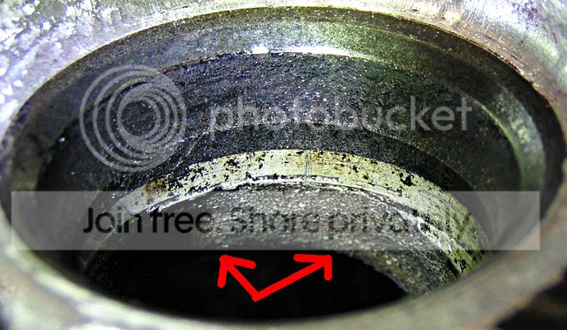
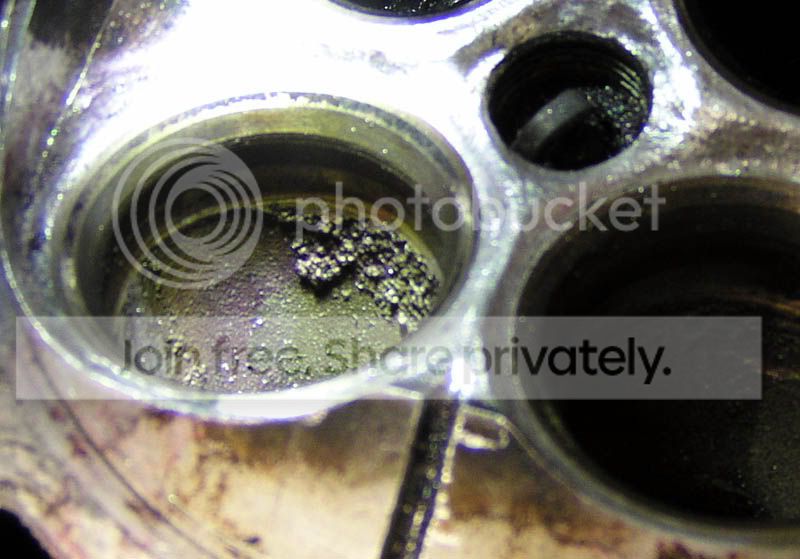
Pics! Here is what you are starting with. All 8 exhaust ports are about the same as far as I can tell, so I'll just show you one.
First, the ports are symmetrical. Some Honda ports point off to one side or the other, but these apparently point straight out from the chamber to the side of the head.
That means, unfortunately, that all the ports have the same problem: a big step/lip where the machining for the valve seat stops in the exhaust ports:

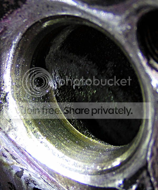
Here is a close-up looking down the runner from the manifold side, at the runner-side of the seat. Notice the shadow running all the way around? There's a big setback hiding in that shadow.
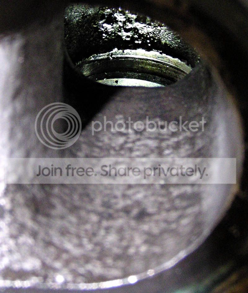
You may have already noticed that the far-inside (toward the middle of the chamber-side) wall of the port is covered in some pretty gnarly casting flash. If not, look at the above pictures again, and then dig this: both sides have flash running down the length of the port, and the step/lip runs all the way around the backside of the valve seat.


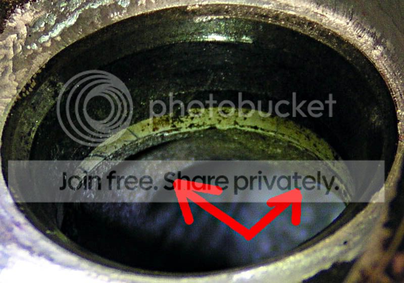
So that's pretty ugly, right there. Then, when the gas tumbles out past that, there are two more sets of obstacles. The valve guide has a little bowl it sits in, and that channels air right to the trough all the way around the valve guide. It's a little hard to shoot the shape of the depression in the port wall leading up to the guide
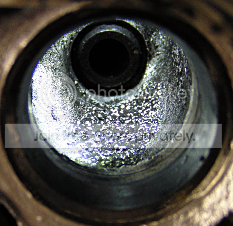
but here you can plainly see the trough around it. I would say that's at least 1mm deep. Note that the trough as well as most of the slope leading to it were completely FULL of carbon when I got this head. It actually made a shape that looked like it would flow half-decent. Which goes to show you just how bad the stock head actually flows: the heavier stuff has a place to drop-out and accumulate before it even starts to make the first turn.
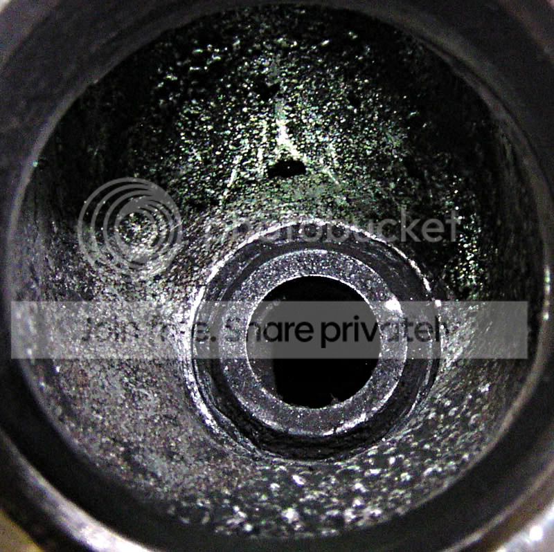
Also, and I don't think this is really a big problem, there is a little trough on either side of the valve guide boss. Here you can kind-of see it on the outside of the port (top-right in this photo), and you can also see what the other side of the valve guide looks like. The boss is pretty well blended into the port as-cast so that's nice anyway.
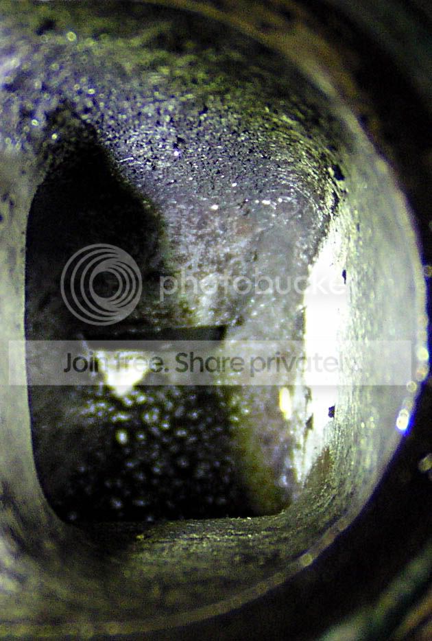
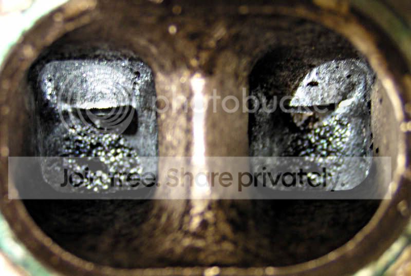
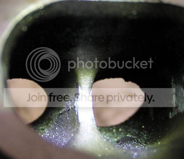
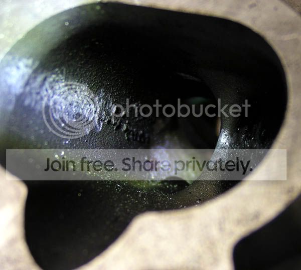
Here's the second problem: a couple of funky divots cast right into the short side radius of the turn. This is the place where most of the air is going to attempt to flow through. This is where the air wants to be moving the fastest in the entire exhaust runner. This should be a nice, smooth turn. Preferably there should be a smooth transition from the valve seat around to the floor of the port. What you have instead is this:
A step for it to tumble over, then a pair of depressions in the corner that will (instead of promoting laminar flow) tend to kick the air up higher into the port, generating all sorts of ugly vortices and slowing down the air that was already going slow around the long (top) side of the port. Nice eh?
********
So there it is. It's a right nasty mess we have to start with. If I had a good welder, I'd have them fill in the step behind the valve seat on the long side and blend it about halfway up to the valve guide boss. But I don't. I am inclined to say that I should just smooth out the flash and leave the step back to the wall on that side alone. The sides of the ports, I am thinking, should be gradually blended from the valve seat to the wall of the port to get rid of the step at the back of the valve seat.
That is to say, leave the step on the side of the port closest to the center of the chamber, and eliminate the step on the side of the port closest to the exhaust manifold, and blend the transition so that the step starts to disappear completely somewhere around the middle/side of the circumference of the seat seat on both sides.
Then smooth out those two depressions on the short side of the turn. I think removing enough material to get rid of the step and depressions will probably be plenty to also make the radius of the turn much less sharp without having to come up with a jig or form to make sure they are all uniform. If it looks and feels like all the opening are about the same after those steps and funky shapes are dealt with, I just might call that short side of the turn 'taken care of'. It would be nice to have a robot to measure it for me and make a CAD shape of each port and tell me what needs to be reshaped to make them all exactly the same, but I don't. I have my fingers and eyes and maybe some cardboard or plastic to cut out to make crude measurement aids, and that's it. So guess what I'll use?
Then remove the trough around the valve guide. This is not a place to make big gains, so I'm likely not going to try to streamline the valve guide or its boss... just remove the step around the guide and round off the corner that will make.
Then polish the entire port to a fairly high degree. Done.
Pics! Here is what you are starting with. All 8 exhaust ports are about the same as far as I can tell, so I'll just show you one.
First, the ports are symmetrical. Some Honda ports point off to one side or the other, but these apparently point straight out from the chamber to the side of the head.
That means, unfortunately, that all the ports have the same problem: a big step/lip where the machining for the valve seat stops in the exhaust ports:
Here is a close-up looking down the runner from the manifold side, at the runner-side of the seat. Notice the shadow running all the way around? There's a big setback hiding in that shadow.
You may have already noticed that the far-inside (toward the middle of the chamber-side) wall of the port is covered in some pretty gnarly casting flash. If not, look at the above pictures again, and then dig this: both sides have flash running down the length of the port, and the step/lip runs all the way around the backside of the valve seat.
So that's pretty ugly, right there. Then, when the gas tumbles out past that, there are two more sets of obstacles. The valve guide has a little bowl it sits in, and that channels air right to the trough all the way around the valve guide. It's a little hard to shoot the shape of the depression in the port wall leading up to the guide
but here you can plainly see the trough around it. I would say that's at least 1mm deep. Note that the trough as well as most of the slope leading to it were completely FULL of carbon when I got this head. It actually made a shape that looked like it would flow half-decent. Which goes to show you just how bad the stock head actually flows: the heavier stuff has a place to drop-out and accumulate before it even starts to make the first turn.
Also, and I don't think this is really a big problem, there is a little trough on either side of the valve guide boss. Here you can kind-of see it on the outside of the port (top-right in this photo), and you can also see what the other side of the valve guide looks like. The boss is pretty well blended into the port as-cast so that's nice anyway.
Here's the second problem: a couple of funky divots cast right into the short side radius of the turn. This is the place where most of the air is going to attempt to flow through. This is where the air wants to be moving the fastest in the entire exhaust runner. This should be a nice, smooth turn. Preferably there should be a smooth transition from the valve seat around to the floor of the port. What you have instead is this:
A step for it to tumble over, then a pair of depressions in the corner that will (instead of promoting laminar flow) tend to kick the air up higher into the port, generating all sorts of ugly vortices and slowing down the air that was already going slow around the long (top) side of the port. Nice eh?
********
So there it is. It's a right nasty mess we have to start with. If I had a good welder, I'd have them fill in the step behind the valve seat on the long side and blend it about halfway up to the valve guide boss. But I don't. I am inclined to say that I should just smooth out the flash and leave the step back to the wall on that side alone. The sides of the ports, I am thinking, should be gradually blended from the valve seat to the wall of the port to get rid of the step at the back of the valve seat.
That is to say, leave the step on the side of the port closest to the center of the chamber, and eliminate the step on the side of the port closest to the exhaust manifold, and blend the transition so that the step starts to disappear completely somewhere around the middle/side of the circumference of the seat seat on both sides.
Then smooth out those two depressions on the short side of the turn. I think removing enough material to get rid of the step and depressions will probably be plenty to also make the radius of the turn much less sharp without having to come up with a jig or form to make sure they are all uniform. If it looks and feels like all the opening are about the same after those steps and funky shapes are dealt with, I just might call that short side of the turn 'taken care of'. It would be nice to have a robot to measure it for me and make a CAD shape of each port and tell me what needs to be reshaped to make them all exactly the same, but I don't. I have my fingers and eyes and maybe some cardboard or plastic to cut out to make crude measurement aids, and that's it. So guess what I'll use?
Then remove the trough around the valve guide. This is not a place to make big gains, so I'm likely not going to try to streamline the valve guide or its boss... just remove the step around the guide and round off the corner that will make.
Then polish the entire port to a fairly high degree. Done.
Thread Starter
Super Moderator
Joined: Sep 2001
Posts: 10,795
Likes: 5
From: Pflugerville, TX
Vehicle: 2000 Elantra
Wow that first set of exhaust valves must have had a leaking stem seal or something! The other 3 cylinders had as much baked-on gunk all put together as that one did. In other news I finally got another 80 minutes in and knocked the big chunks out of the rest of the exhaust bowls. I found out that isopropanol will soften up the hard parts of the oil/carbon fouling just enough to chip it out, which is why I was able to clean out around the valve guides, otherwise it would have been nearly impossible. When you get the majority of the big chunks of coke out, get a brass-bristled brush and some isopropyl alcohol and scrub a little, then wipe the runner with a paper towel. You should be able to see what is still covered in gunk and what's not.
No pics tonight, but this is not a dead thread (yet) either.
No pics tonight, but this is not a dead thread (yet) either.

Thread Starter
Super Moderator
Joined: Sep 2001
Posts: 10,795
Likes: 5
From: Pflugerville, TX
Vehicle: 2000 Elantra
PM me, we might have a potential car pool here. It never hurts to check, right?
When this head gets done, you can be sure I'll post about it here, even if my slippy memory doesn't get in touch (but I'll try to remember)
When this head gets done, you can be sure I'll post about it here, even if my slippy memory doesn't get in touch (but I'll try to remember)
Thread Starter
Super Moderator
Joined: Sep 2001
Posts: 10,795
Likes: 5
From: Pflugerville, TX
Vehicle: 2000 Elantra
Chalk up another 4 hours of work on this head. Intake runners and then bowls this time. The runners were first. They had already been worked on a little, but I went and got the rest of the casting flash and spatter down along the sides, as well as hitting any random stuff sticking out into the runners. The focus in these pictures is a little off, but that's why every camera should have manual focus ability. Oh well thank God for a free camera!
Before:
Inside
Outside
After:
Inside

Outside

Then I went to the top of the runner/intake bowl area and took out the flash as best I could. There is still a bit of a lip where the seat pokes out into the runner, but I am inclined to not cut the seat and leave the lip. It is already way better than it used to be, and this is only the top side (lower airflow). These all started pretty jacked up from the factory, and they were all a little different. I took a few shots just so you could see the different kinds of bad there were in there. The last before and the after are of the same bowl, but they all ended up looking pretty much alike (which was the idea).
Before:

After:

Then I moved on to the short side of the turn, where the air moves fastest into the chamber. This is one of the more important transitions for good efficiency in the head. Of course, Hyundai went ahead and left a lip and a few pieces of casting flash right there.
I was thinking I would try to widen the floor of the intake runners a little, in the middle of this turn. As it turns out, it was necessary to widen the floor a little, just to get the transition smooth on the sides. Where there used to be a lip, now there is a round-over straight to the valve seat insert. Good.

At this point, I also finished dressing down the casting flash on the sides of the runners, in the bowl area. You can tell when you are doing this, using (preferably) an LED flashlight, where there are high spots in the runner. The high spots cast shadows.
One note of caution for would-be head porters out there: ALL of the work in the bowls so far was done through from the chamber side. Spinning tungsten carbide bits require caution during repeated insertion and removal through the valve seat insert. One false move and you will need a valve job whether you needed one before, or not. I think I am okay there, but I was getting tired before I decided to call it a night, and there were a couple of close calls. I pray I will be able to finish this head without really goobering up any of the valve seating surfaces. We'll see. The exhaust valves are tiny and getting down in there will be that much harder, so I'm glad I got to practice on the intake side first.
I did, and you might want to, wrap the jaws of your tool (that hold the actual cutting bit) in vinyl electrical tape to protect the valve seats from the chuck when (not if) you slip up and let the chuck hit the seat by angling the tool the wrong way into the bowl.
The intake runners and bowls are almost roughed-in. I need to go have a look at what the valve guides look like in the runners and they may very well be left alone. I also need to go through and leave some texture all the way down the runner and in the bowl, to try to discourage fuel dropout. I am still undecided as to what to do about the (now much-reduced) step on the top of the port, where it meets the valve seat. My instincts tell me to leave it.
Before:
Inside
Outside
After:
Inside
Outside
Then I went to the top of the runner/intake bowl area and took out the flash as best I could. There is still a bit of a lip where the seat pokes out into the runner, but I am inclined to not cut the seat and leave the lip. It is already way better than it used to be, and this is only the top side (lower airflow). These all started pretty jacked up from the factory, and they were all a little different. I took a few shots just so you could see the different kinds of bad there were in there. The last before and the after are of the same bowl, but they all ended up looking pretty much alike (which was the idea).
Before:
After:
Then I moved on to the short side of the turn, where the air moves fastest into the chamber. This is one of the more important transitions for good efficiency in the head. Of course, Hyundai went ahead and left a lip and a few pieces of casting flash right there.
I was thinking I would try to widen the floor of the intake runners a little, in the middle of this turn. As it turns out, it was necessary to widen the floor a little, just to get the transition smooth on the sides. Where there used to be a lip, now there is a round-over straight to the valve seat insert. Good.
At this point, I also finished dressing down the casting flash on the sides of the runners, in the bowl area. You can tell when you are doing this, using (preferably) an LED flashlight, where there are high spots in the runner. The high spots cast shadows.
One note of caution for would-be head porters out there: ALL of the work in the bowls so far was done through from the chamber side. Spinning tungsten carbide bits require caution during repeated insertion and removal through the valve seat insert. One false move and you will need a valve job whether you needed one before, or not. I think I am okay there, but I was getting tired before I decided to call it a night, and there were a couple of close calls. I pray I will be able to finish this head without really goobering up any of the valve seating surfaces. We'll see. The exhaust valves are tiny and getting down in there will be that much harder, so I'm glad I got to practice on the intake side first.
I did, and you might want to, wrap the jaws of your tool (that hold the actual cutting bit) in vinyl electrical tape to protect the valve seats from the chuck when (not if) you slip up and let the chuck hit the seat by angling the tool the wrong way into the bowl.
The intake runners and bowls are almost roughed-in. I need to go have a look at what the valve guides look like in the runners and they may very well be left alone. I also need to go through and leave some texture all the way down the runner and in the bowl, to try to discourage fuel dropout. I am still undecided as to what to do about the (now much-reduced) step on the top of the port, where it meets the valve seat. My instincts tell me to leave it.
Thread Starter
Super Moderator
Joined: Sep 2001
Posts: 10,795
Likes: 5
From: Pflugerville, TX
Vehicle: 2000 Elantra
After a pair of 45-minute sessions, three exhaust runners have had the divots ground out of the short side radius. It involved the removal of quite a bit of material from the bowl and the floor and sides of the runner, and the shape is changed quite a bit. The corners are closer to square than they used to be, and the floor has been lowered a little through the turn. I was wondering what I could do to ensure that the shapes of the ports were uniform all the way across the head, but it turns out I need not have. I think just removing the dips and corners around the short-side radius will be all the material removal I wanted to do. Rounding off the corner this way leads to an increased cross-section of the runner through the bend. . . which is, you will recall, where the valve stem pokes through and the valve guide boss takes up a bunch of room in the bend.
There used to be a sharp corner around 1/4" down from the valve seat, but that's gone now, and the main transition now is the last angle on the valve seat insert. After that, it's a curve until you get as far around the bend as my carbide brush/cutter will take it. Then there's a corner that will be taken out with a ball mill or something, later.
I'm going to have to research whether or not it will affect reliability to round off that last step on the valve seat insert, because then the sharpest angles would be around the valve sealing surface and that's good enough for me (for now, I think wink1.gif ).
Sorry, no pictures just yet, thanks to dead camera batteries.