
My Head Has Holes In It. They Need A Port And Polish!

Thread Starter
Super Moderator


Joined: Sep 2001
Posts: 10,795
Likes: 5
From: Pflugerville, TX
Vehicle: 2000 Elantra
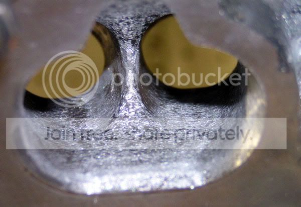
Another couple of hours later, and all the exhaust ports are now shaped about alike. They all need the corner of the short side radius dressed round, but I know you want in-progress pictures.
The most obvious change is a fairly different shape around the bend. As you can see, the port has a wider floor, and it is lower toward the divider between the ports. If I had a good aluminum welding rig, I should have liked to put a little bead in each of those divots I showed you earlier. As it is, the 'outside' divot is gone and the inside divot is eliminated nearly enough for my liking.
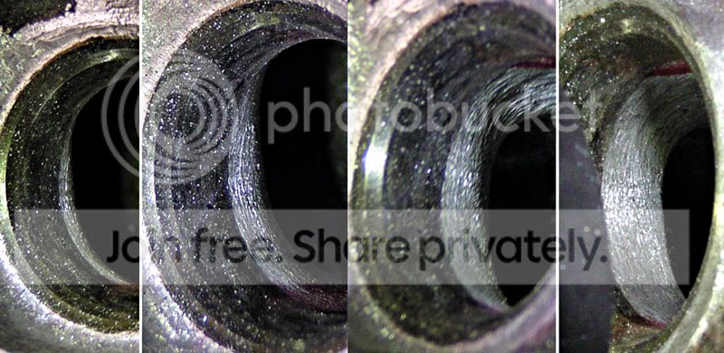
This is the blending I was talking about, on the ridge around the long side of the turn / top of the port. There was a little bit of flash around the inside of the ridge behind the valve seat insert. The red marker was to show me where I had removed material. I didn't want to eliminate the ridge behind the insert altogether (yet?) but I figured a piece of flash poking out into the airflow wouldn't be good in any case. The ridge is, as I hoped to be able to make it, blended away right around the middle of each side of the port.
The valve guide boss still has a big lip around it. On the upstream side this is unavoidable without installing a much-fatter/longer guide or doing some welding (not gonna happen). The downstream side lip around the valve guide looks like it can be removed fairly easily and I plan to just knock it flush with the machined valve guide pocket. I would leave this alone, but then I recall it was packed full of carbon gunk when I tore the head down.

Here's the view of the valve guide boss from the port side, for future reference.

I still intend to sharpen the port divider on the exhaust side. Leading edges of airfoils are round, but trailing edges are sharp, eh?
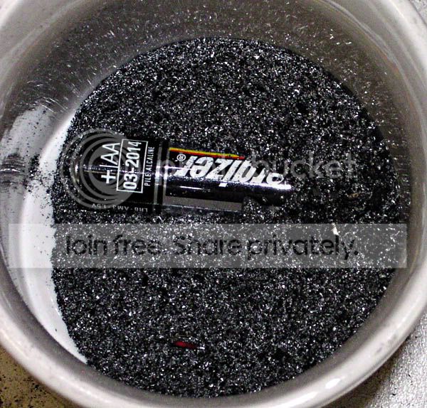
Note: one of the reasons this takes a while is that the tool takes an infinitesimal amount of material out with each stroke. These little teeth:

Took all this out of the exhaust bowls. That's a regular coffee mug and a "AA" battery.
I just spent a few minutes with a 1/8" ball mill and came to an important realization: that 'before' shot of the valve guide boss is going to show up a pretty radical change of shape to the roof of the ports on the exhaust side (haven't checked the intake side for this yet)
The little groove between the guide and its boss that I thought was ~1mm deep? Yeah, try more like 3mm, at least. Removing that little lip takes the boss from a shape that will flow pretty nice when the gap is full of carbon and oil gunk, to something with a nasty square edge right where the flow is trying to go high in the port.
Watch this space for extensively-reworked valve guide bosses. I went and looked to see what Endyn does on their bosses . . . it ain't exactly left alone! The radius and fairing-in to the port roof is pretty thorough, and about matches what I wanted to do. Great minds think alike? nana.gif
I'm thinking, maybe round the edges a lil' bit but leave most of the valve guide for strength/durability.
Here I thought I was almost done with changing shapes. Oh well.
The most obvious change is a fairly different shape around the bend. As you can see, the port has a wider floor, and it is lower toward the divider between the ports. If I had a good aluminum welding rig, I should have liked to put a little bead in each of those divots I showed you earlier. As it is, the 'outside' divot is gone and the inside divot is eliminated nearly enough for my liking.
This is the blending I was talking about, on the ridge around the long side of the turn / top of the port. There was a little bit of flash around the inside of the ridge behind the valve seat insert. The red marker was to show me where I had removed material. I didn't want to eliminate the ridge behind the insert altogether (yet?) but I figured a piece of flash poking out into the airflow wouldn't be good in any case. The ridge is, as I hoped to be able to make it, blended away right around the middle of each side of the port.
The valve guide boss still has a big lip around it. On the upstream side this is unavoidable without installing a much-fatter/longer guide or doing some welding (not gonna happen). The downstream side lip around the valve guide looks like it can be removed fairly easily and I plan to just knock it flush with the machined valve guide pocket. I would leave this alone, but then I recall it was packed full of carbon gunk when I tore the head down.
Here's the view of the valve guide boss from the port side, for future reference.
I still intend to sharpen the port divider on the exhaust side. Leading edges of airfoils are round, but trailing edges are sharp, eh?
Note: one of the reasons this takes a while is that the tool takes an infinitesimal amount of material out with each stroke. These little teeth:
Took all this out of the exhaust bowls. That's a regular coffee mug and a "AA" battery.
I just spent a few minutes with a 1/8" ball mill and came to an important realization: that 'before' shot of the valve guide boss is going to show up a pretty radical change of shape to the roof of the ports on the exhaust side (haven't checked the intake side for this yet)
The little groove between the guide and its boss that I thought was ~1mm deep? Yeah, try more like 3mm, at least. Removing that little lip takes the boss from a shape that will flow pretty nice when the gap is full of carbon and oil gunk, to something with a nasty square edge right where the flow is trying to go high in the port.
Watch this space for extensively-reworked valve guide bosses. I went and looked to see what Endyn does on their bosses . . . it ain't exactly left alone! The radius and fairing-in to the port roof is pretty thorough, and about matches what I wanted to do. Great minds think alike? nana.gif
I'm thinking, maybe round the edges a lil' bit but leave most of the valve guide for strength/durability.
Here I thought I was almost done with changing shapes. Oh well.
Thread Starter
Super Moderator
Joined: Sep 2001
Posts: 10,795
Likes: 5
From: Pflugerville, TX
Vehicle: 2000 Elantra
I've spent another couple of hours on this project. In each exhaust port:
*The exhaust valve seat boss has been cut down a difficult-to-measure 2-3mm and faired out into the roof of each port
*Exhaust valve guides are rounded over a little on the outside. I may revisit the inside later
*Exhaust runner sides/tops are about as polished as they are going to get, which is to say, they have been burnished by my ball mill tip. the port floors are going to be burnished after I finish rounding off the turn on the short/floor radius in the elbow of the port
I figured out that a long stip of sandpaper (using 220 grit) is probably the best tool I have for eliminating the sharp SSR corner. I got one pair of ports rounded off with it, and I had a silly grin on my face the first time I ran a finger from the valve seat to the floor of the runner & I felt it all one continuous smooth curve.
*I need to burnish/polish the exhaust bowls after the corners are rounded. Then the exhaust ports will be "done."
*Without a header to port-match to I am going to leave the stock opening size on the exhaust ports. I do have an intake manifold to which I intend to port-match the intake ports.
*Pictures when the exhaust ports are done.
Thread Starter
Super Moderator
Joined: Sep 2001
Posts: 10,795
Likes: 5
From: Pflugerville, TX
Vehicle: 2000 Elantra
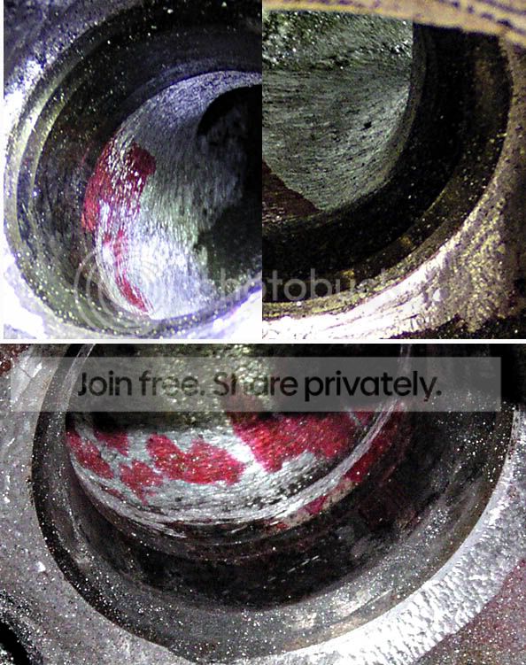
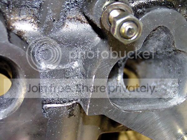
The work has progressed beyond this point, but this is all I have photos of (and time to write up) for now. The first image is a composite, which is why the colors change abruptly at a scraggly line in the middle of the port.
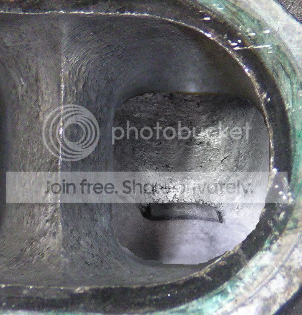

The exhaust runner divider in each exhaust port has been knife-edged. Literally. Sharp.
Flash and offset left over from the casting process have been eliminated.
The valve guide boss I told you to remember? A few millimeters were taken off the top of it.
The funky short-side corner has been rounded. It is round now, from the valve seat to the floor of the port. For this work, I used 2-3 foot long sections of 220 grit wet sandpaper.
The only polishing compound I have on hand is for coloring steel, but it cuts aluminum well enough to knock all the high spots off, which is good enough for me. I used a felt buff on my dremel to get all the way down the ports. I missed one spot on the port floor on every runner but the rest of the ports are pretty smooth all over. I consistently missed that one spot because my procedure throughout this whole affair has been to do one thing to all cylinders at once, then move on to the next. Obviously I need to add a "polish that spot" step in there wink1.gif
The overhang on the inside of the valve seat is still there, but the gravelly texture is not. The bowl is smoother now by a LOT. Without a good welder, I'm leaving it like that.
So there it is. The exhaust ports, aside from one small spot in each as noted above, are finished as far as I'm concerned. I've moved on to sanding down the combustion chambers, which is going to take . . . a while.
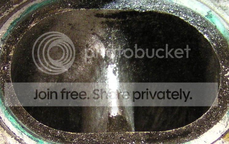
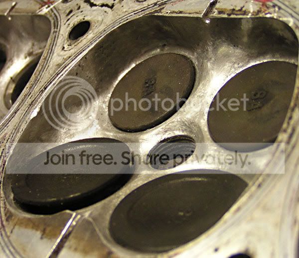
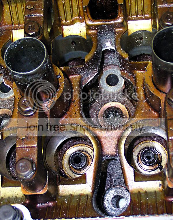
For those who may be curious, here are a few slightly out of focus shots (from iheartmyRD) of stock combustion chambers that have been cleaned. All those corners fill with carbon gunk eventually, which you saw in my cylinder head a while back.


The exhaust runner divider in each exhaust port has been knife-edged. Literally. Sharp.
Flash and offset left over from the casting process have been eliminated.
The valve guide boss I told you to remember? A few millimeters were taken off the top of it.
The funky short-side corner has been rounded. It is round now, from the valve seat to the floor of the port. For this work, I used 2-3 foot long sections of 220 grit wet sandpaper.
The only polishing compound I have on hand is for coloring steel, but it cuts aluminum well enough to knock all the high spots off, which is good enough for me. I used a felt buff on my dremel to get all the way down the ports. I missed one spot on the port floor on every runner but the rest of the ports are pretty smooth all over. I consistently missed that one spot because my procedure throughout this whole affair has been to do one thing to all cylinders at once, then move on to the next. Obviously I need to add a "polish that spot" step in there wink1.gif
The overhang on the inside of the valve seat is still there, but the gravelly texture is not. The bowl is smoother now by a LOT. Without a good welder, I'm leaving it like that.
So there it is. The exhaust ports, aside from one small spot in each as noted above, are finished as far as I'm concerned. I've moved on to sanding down the combustion chambers, which is going to take . . . a while.
For those who may be curious, here are a few slightly out of focus shots (from iheartmyRD) of stock combustion chambers that have been cleaned. All those corners fill with carbon gunk eventually, which you saw in my cylinder head a while back.
Thread Starter
Super Moderator
Joined: Sep 2001
Posts: 10,795
Likes: 5
From: Pflugerville, TX
Vehicle: 2000 Elantra
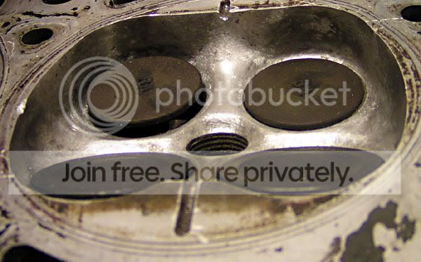
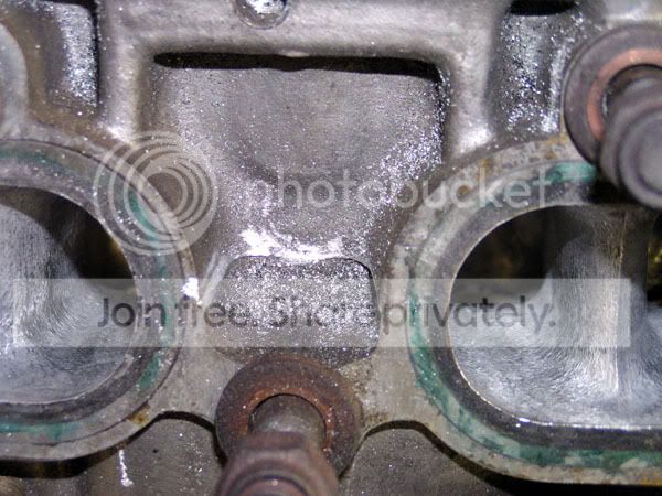
Finally got around to processing the photos of the combustion chambers.
This is about as "finished" as I am inclined to make them. Note to those who wanted to see mirror polished chambers: this is 1000x better than when it started. If you really want them more polished than this, you are welcome to come do the sanding yourself. This is after 200 grit dry sanding.
Two overall views:
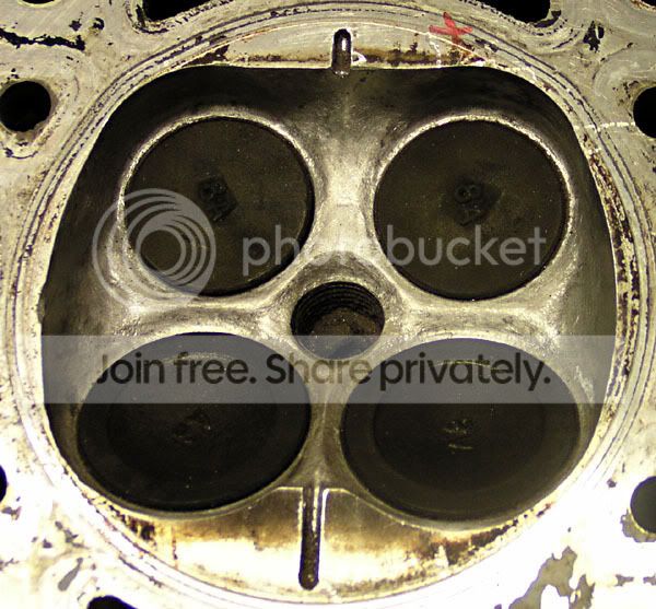
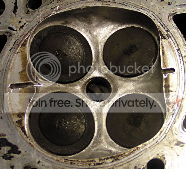
Exhaust side
Exhaust valve clearance:
Intake side
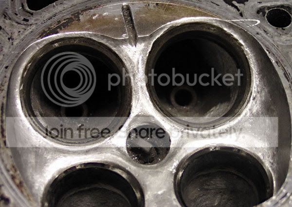
Intake valve clearance:
And that right there is a huuuuuge improvement over what I found when this head was pulled off the engine!
I still want to port-match the intake runners to the intake manifold (with anti-reversion step, remember) and 80-grit the entire intake port to promote atomization. I need a full set of OEM valves, preferably cheap (hint to anyone with a spare head) and then I can see if I can get away with just lapping the valves to their seats or else it's valve job time. Need to grind the text off the valve faces ( ! ) and alter the profiles on the backs of the valves, rounding the angles just a little bit. Then I need to get the head decked, re-cut the Singh grooves, and install a fresh set of valve stem seals.
Port/polish as much of the intake manifold as I feel like, buy new gaskets 02.gif and then I'll FINALLY be ready to install this head! Note: unless somebody wants to donate several hundred $ to The Cause, this is still several months away due to having to pay off CC debt instead of buying parts owned.gif
This is about as "finished" as I am inclined to make them. Note to those who wanted to see mirror polished chambers: this is 1000x better than when it started. If you really want them more polished than this, you are welcome to come do the sanding yourself. This is after 200 grit dry sanding.
Two overall views:
Exhaust side
Exhaust valve clearance:
Intake side
Intake valve clearance:
And that right there is a huuuuuge improvement over what I found when this head was pulled off the engine!
I still want to port-match the intake runners to the intake manifold (with anti-reversion step, remember) and 80-grit the entire intake port to promote atomization. I need a full set of OEM valves, preferably cheap (hint to anyone with a spare head) and then I can see if I can get away with just lapping the valves to their seats or else it's valve job time. Need to grind the text off the valve faces ( ! ) and alter the profiles on the backs of the valves, rounding the angles just a little bit. Then I need to get the head decked, re-cut the Singh grooves, and install a fresh set of valve stem seals.
Port/polish as much of the intake manifold as I feel like, buy new gaskets 02.gif and then I'll FINALLY be ready to install this head! Note: unless somebody wants to donate several hundred $ to The Cause, this is still several months away due to having to pay off CC debt instead of buying parts owned.gif
Thread Starter
Super Moderator
Joined: Sep 2001
Posts: 10,795
Likes: 5
From: Pflugerville, TX
Vehicle: 2000 Elantra
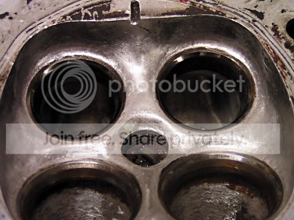
Update w/ photos.
I roughed up the intake ports a little to promote atomization.
Then I cleaned up some of the external casting flash.
Between intake runners:
Between exhaust runners:
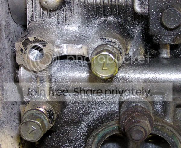
On the ends, including the end of the oil gallery:
On the power steering pump mounting boss (I debated removing the boss altogether but decided not to for now):
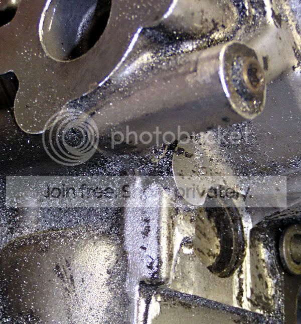
Up in the valvetrain area, there is a LOT of flash. It can't do anything but slow down oil return, so I cut a bunch of it out:
Still need to:
*Measure and match chamber volumes
*Waiting on valves from one of the members here, then I'll try to lap the valves to their seats, or else it's a valve job at the same time as the
*Deck gets 1/2 to 1mm cut off the bottom depending on how big the chambers are now
*Then re-cut Singh grooves
Then I need to buy rings and gaskets, clean up pistons, still debating whether or not to work on the intake manifold or sell it, then slap 'er in there!
getting closer. . .
I roughed up the intake ports a little to promote atomization.
Then I cleaned up some of the external casting flash.
Between intake runners:
Between exhaust runners:
On the ends, including the end of the oil gallery:
On the power steering pump mounting boss (I debated removing the boss altogether but decided not to for now):
Up in the valvetrain area, there is a LOT of flash. It can't do anything but slow down oil return, so I cut a bunch of it out:
Still need to:
*Measure and match chamber volumes
*Waiting on valves from one of the members here, then I'll try to lap the valves to their seats, or else it's a valve job at the same time as the
*Deck gets 1/2 to 1mm cut off the bottom depending on how big the chambers are now
*Then re-cut Singh grooves
Then I need to buy rings and gaskets, clean up pistons, still debating whether or not to work on the intake manifold or sell it, then slap 'er in there!
getting closer. . .
Thread Starter
Super Moderator
Joined: Sep 2001
Posts: 10,795
Likes: 5
From: Pflugerville, TX
Vehicle: 2000 Elantra
I never thought about it that way, but it makes sense that it would help with bolt installation/removal. Thanks.
I mentioned it to another member in a PM conversation so I guess I'll say it here too.
The intake runners in the head have an intentional restriction. If you look at those last intake runner shots you will be able to see a protrusion all the way around, right at the inlet of the runner. It has just a little bit of a bottle-neck. This is the area where the fuel injectors spray. That bump decreases the runner cross-section slightly and increases flow velocity accordingly. That is for fuel atomization. Fuel atomization is good. You want that.
Some people have advocated grinding out the ends of the runners in the intake manifold, and the beginnings of the runners on the intake side of the head, to match the opening size in an intake gasket. This is a bad idea* for a couple of reasons.
You want a small step, with the opening in the head a hair larger (say 0.070") than the hole in the IM. When the intake valves slam shut, a little puff of air comes up, and it meets the air streaming in trying to get into the combustion chamber. They gang up and try to go back up the intake runner and up into the IM again when the intake valve is closed. When there is a small anti-reversion step, the reversing air has a restriction to help it not go so freely back up the intake manifold. That's a good thing. During the intake stroke when air is going into the engine, a SMALL step will have a boundary layer in it, and the flow will not be greatly disturbed. My spare IM has openings slightly smaller than the openings in the head. The size difference is not consistent all the way around, but it is there.
If you gasket match the head and IM openings, you are not only eliminating an anti-reversion step, you are eliminating an atomization-promoting high velocity area in the head. For a naturally aspirated engine setup including nitrous use, that is bad.
*If you are going with forced induction and your goal is max HP and you can afford to lose a little low end torque (relatively speaking) then go ahead and gasket match this joint. You will have a less-restricted intake tract. If you are going that far, I hope you also do a full P&P on your head because, well, you've seen what they look like inside the head, stock.

Moderator

Joined: Mar 2009
Posts: 5,280
Likes: 0
From: wamego, kansas
Vehicle: 2001 hyundai tiburon
coudl you by chance give the stock numbers on the dremel attachments that you have been using? i know you have said the sizes but it may be easier to know the #'s of the various tools you are using on this. i am kind of interested on this myself since i always need spomething to tinker with. thanks in advance.
Thread Starter
Super Moderator
Joined: Sep 2001
Posts: 10,795
Likes: 5
From: Pflugerville, TX
Vehicle: 2000 Elantra
haha this will keep you tinkering for weeks!
I couldn't tell you the numbers. Most of them I've had for years. I think mostly I used a 1/8 and 3/16" ball mill, and the carbide burr. If you could swing for a set of port/polish abrasives from a company like Eastwood, that would probably get you a faster result, if not necessarily a better one. My dad gave me one of his rubberized abrasive stones that was too big to do anything but the wall by the exhaust valves and it sped the smoothing of that wall tremendously.
The most important parts of the whole setup actually are the long flexible attachment shaft and the variac I'm using to slow the motor to a crawl. You can make-do with different cutters sometimes, but if you can't reach the work area or can't control the cutter, it's all worthless.
Moderator
Joined: Mar 2009
Posts: 5,280
Likes: 0
From: wamego, kansas
Vehicle: 2001 hyundai tiburon
thanks for the info on the eastwood products, never thought about them. I remember when i changed a gasket on my head cover that i was appauled on how much flashing was left in the head, I MEAN EVERYWHERE!!!! with seeing all the flash i am pretty sure there is more if i were to open it up.