
Electric Supercharger.


Thread Starter
Senior Member
Joined: May 2007
Posts: 869
Likes: 0
Vehicle: 1998 Tiburon
Before I start yes I know they're shit, and yes I know they don't do anything. Well, do they?
OK, after doing months and months of research (it all began last October but I kept it quiet) I have finally got a concept for one that WILL work and WILL produce boost.
It all began when TomOTEC and I bought some plans from the net. We didnt like the look of them because it was all a bit ghetto, and the fact you needed 3 car batteries wasnt that appealing either. And, at the end of it all you would end up with a pretty weak boost anyways.
However, in the months afterwards I *did* find one that provides a nice boost. Problem was it was $2000 lol.
Basically it's a centrifugal but powered by electricity. And it looks just like the front end of a turbo (minus the exhaust housing and wastegate.)
So I went on ebay and bought one of the plastic bilge pumps to give me an insight into what goes on, ended up blowing it up with 40 volts. It wouldnt have worked (and I knew this) because it was made from plastic and concaved when any pressure built. I did have fun blowing things accross the living room until a really bad burning smell came from the motor.. It was $25, the guy selling them only does so to stop people getting ripped off..
Anyway, time to bring you all up to speed. I decided a long time ago that I was going to see this through, and I was going to end up with something that could be ran electrically and pump air into my intake system. I have seen this being done with a leaf blower and it works. I dont want to argue over that, it was Dyno'd and proven.
Now this isnt going to be something anyone can run out and do, remember Im 33 years old and have a EXTREMELY technical background. If I dont know how something works I will get one and spend the day taking it apart to figure it out. By the end of the day I know *EXACTLY* what it does.
So I had put my project to one side recently because of everything else I have been doing on the car, but I still had all kinds of shit laying around my apartment ready for the project to kick back into action.
And then yesterday I got the call that has re-ignited the whole affair.. My friend Ryan (with the rather stupidly fast STI wagon) called me and said "dude, I got you a turbo to play with, come and get it"
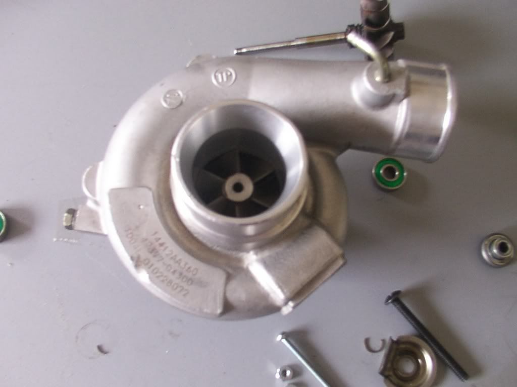
Before anyone plays judge, jury and executioner remember this turbo was spent. All of the bearings had died and there was play in the impellor shaft. Using it as intended would have ended in tears. BUT.. It was all complete and therefore perfect because I didnt need any of that anyways.
So I got over to Ryan's yesterday and began learning what goes into a turbo, what it does and how it works.. Ryan said that they operate around the 25k-30k RPM range and provide a real strong boost there. So we set to taking it apart..
Before we did that however we rigged a 15,000 RPM angle grinder to the exhaust impellor and wound the turbo up. Nice boost of air circulating the garagge LMAO. (P.S DONT try this at home. Even the dust from the garage floor almost took skin of my legs.. We're talking danger here).
So now I knew what I was going to use for the 'motor'.. I have a grinder that produces 18k RPM that I bought to cut my seat brackets... It was $35 and has sat in the box since then. I'm no metalworker...
However, I can already hear the skeptics among us saying "dude, 18k RPM isnt enough" and they're absolutely right. And that's where my skill comes in...
The concept.
I have an immaculate turbo. All that was done on it were the internal bearings. The housing, impellor and parts I need for this are all there.
I also have an angle grinder motor, capable of 18k RPM.
Now, to make this bastard REALLY give off boost Im going to need to double the RPM output of that motor.. How? easy.
I have a back wheel from a mountain bike over @ my uncles, with a good chain. Bike was destroyed when I ran into a ditch and bent the front end, but it has what I need..
So here is what will sit on the back of the now modded turbo -
It's a steel plate with spindles on rollerskate bearings.. (well at the moment its a pic I made in paint). I studied ratios in school and I will be running 2:1. The drive gear will be twice the size of the gear on the spline of the turbo, making me spin around the 36000 RPM mark. And angle grinder motors are INCREDIBLY torquey too, theyre made to cut steel.
So the small gear will go down into the turbo, and the large gear will be on the grinder motor. And the red in the pic is a MTB chain.
And now for what I have to do with the turbo.
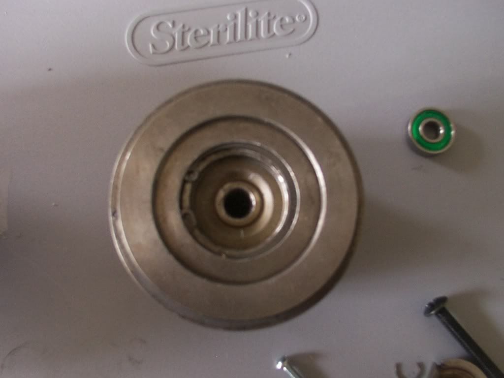
This is the ass end of the rear assembly (Turbo is in 2 halves held together with a large spring clip.. This turbo comes from a MITSU)
The hole in the middle will be skimmed out to hold a rear bearing (also in the pic)

There is a nice lip inside that will stop the bearing from falling in.
And now how the frontal bearing will be held in..
Here is the front end of the rear part of the turbo -
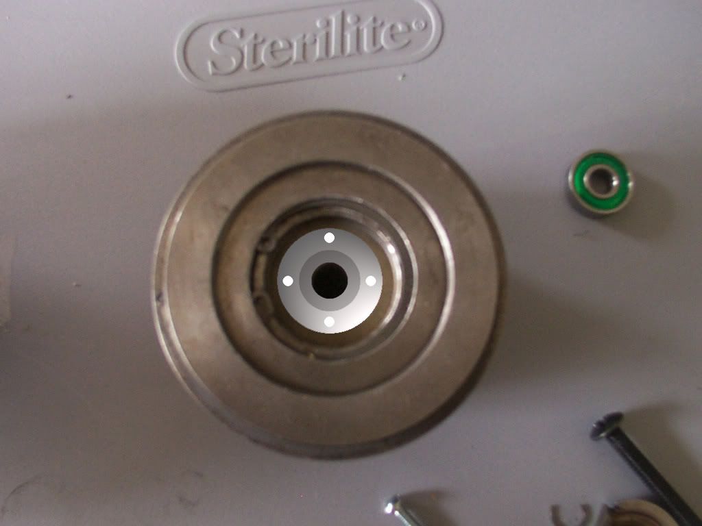
And here is what I will be getting machined.. A bearing cup to hold said frontal bearing.
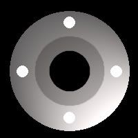
And wehre it sits. 4 holes hold countersunk allen bolts holding it in, bearings press into center..
Here is the worn and snapped spline from the old assembly -
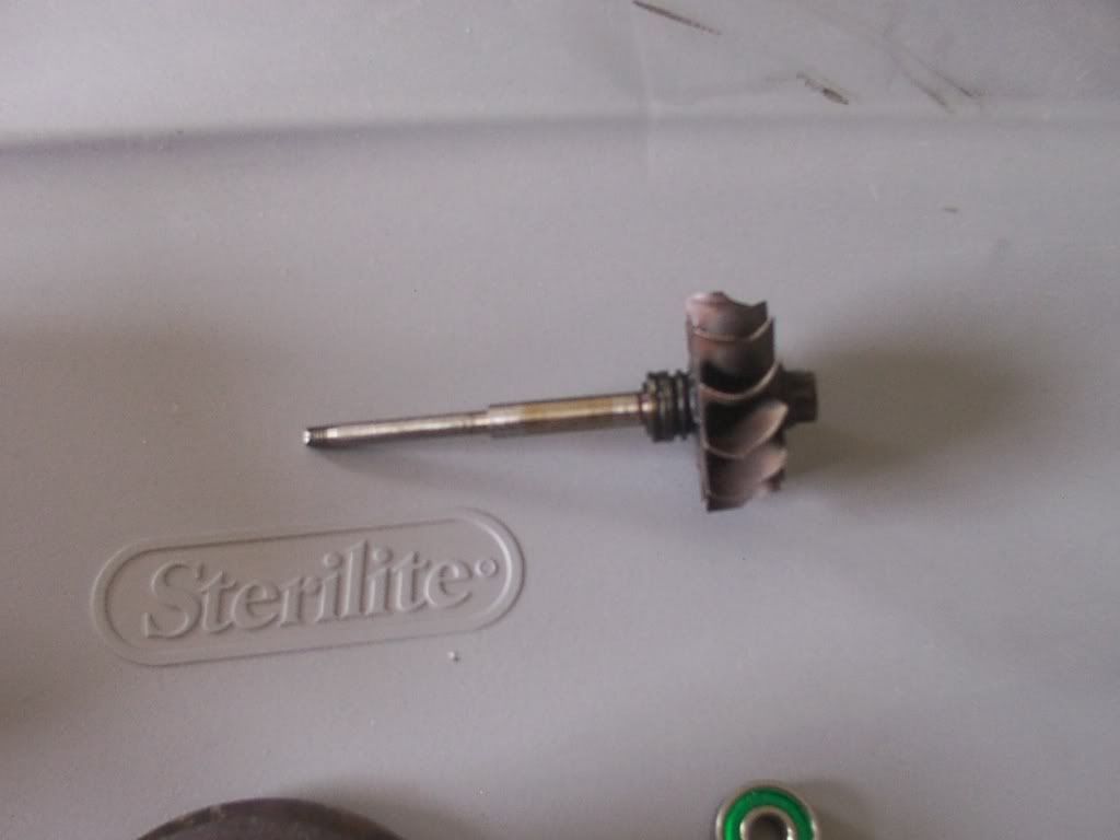
I will be getting one machined that fits snug into the rollerskate bearings (which are ceramic BTW, donated by the same guy who gave me the turbo) At the back end it will protrude out and be welded to the small gear. Front end it will taper in and the impellor will bolt on. It will ride snug inside the bearings, and spin really smooth.
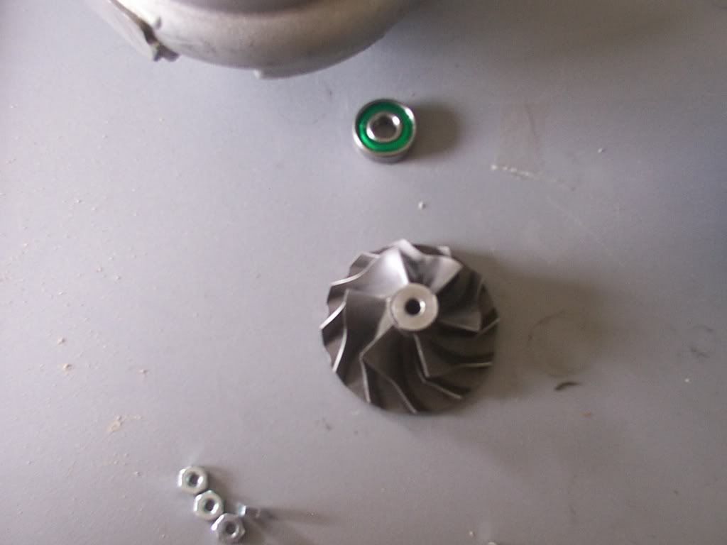
The impellor. This turbo is really well machined.. The diffuser is part of the body.. Thankfully the impellor isnt damaged and pretty much like brand new
Top end of turbo -
Where the impellor rides, 1.5 mm off this housing..
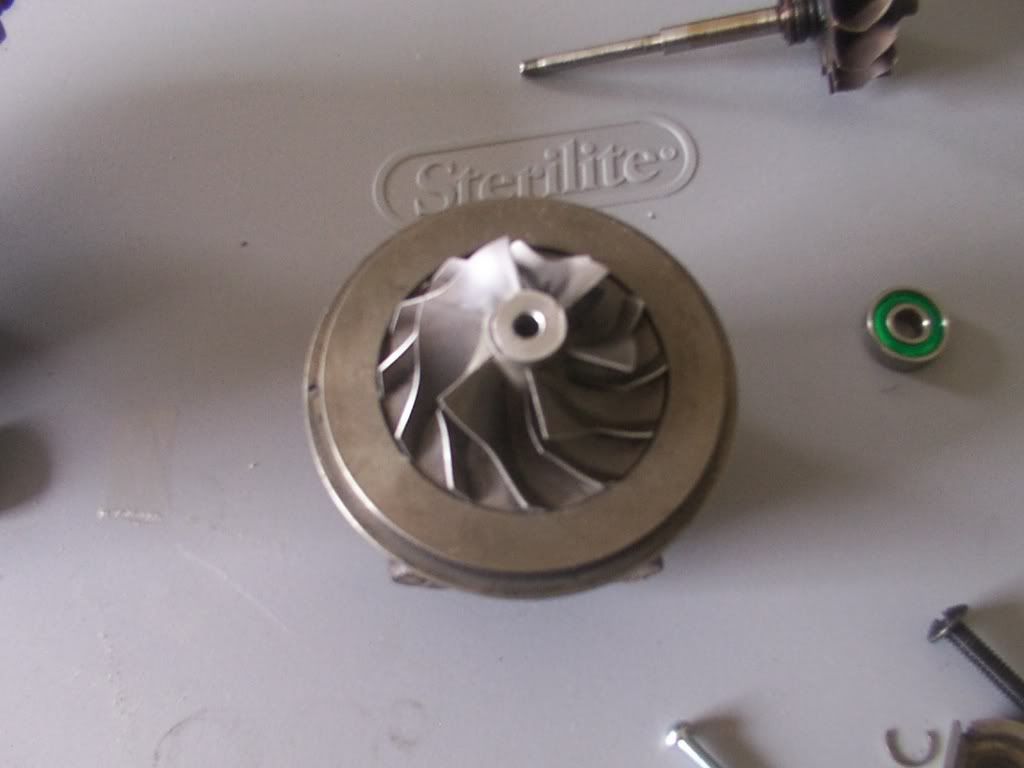
And what it looks like when assembled -
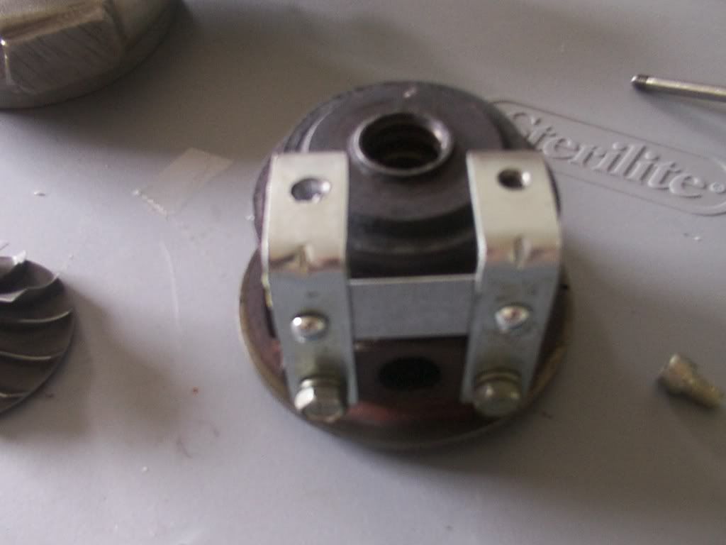
Fabrication has begun and is going well, here is a part of the bracket assembly that will hold the gear/chain/motor assembly onto thr back of the tuebo, basically making it a centrifugal air pump.
And I'll be off to the machine shop soon to get all the parts I need planned out and machined.
I will, of course, keep everyone updated smile.gif
How does one control the ammount of boost pressure with this unit tho? surely it's going to be all or nothing??
No. After alot of brainstorming Ryan and I worked out a very clever, sneaky and cheap way of controlling the boost..
Ever seen a stopcock for a plumbing system? it's basically a faucet but doesnt have a tap, instead it has a red bar that you can twist to shut off the water supply.
This will be welded into an Alu intake tube and on the outlet will be fitted a small air filter. All we need to do then is turn the tap to open/close/adjust the ammount of pressure that we want to be able to come into the air system, depressureising the boost.
The concept of this is identical to a pressure cooker. on the top is a small valve that allows you to release the pressure inside..
OK, after doing months and months of research (it all began last October but I kept it quiet) I have finally got a concept for one that WILL work and WILL produce boost.
It all began when TomOTEC and I bought some plans from the net. We didnt like the look of them because it was all a bit ghetto, and the fact you needed 3 car batteries wasnt that appealing either. And, at the end of it all you would end up with a pretty weak boost anyways.
However, in the months afterwards I *did* find one that provides a nice boost. Problem was it was $2000 lol.
Basically it's a centrifugal but powered by electricity. And it looks just like the front end of a turbo (minus the exhaust housing and wastegate.)
So I went on ebay and bought one of the plastic bilge pumps to give me an insight into what goes on, ended up blowing it up with 40 volts. It wouldnt have worked (and I knew this) because it was made from plastic and concaved when any pressure built. I did have fun blowing things accross the living room until a really bad burning smell came from the motor.. It was $25, the guy selling them only does so to stop people getting ripped off..
Anyway, time to bring you all up to speed. I decided a long time ago that I was going to see this through, and I was going to end up with something that could be ran electrically and pump air into my intake system. I have seen this being done with a leaf blower and it works. I dont want to argue over that, it was Dyno'd and proven.
Now this isnt going to be something anyone can run out and do, remember Im 33 years old and have a EXTREMELY technical background. If I dont know how something works I will get one and spend the day taking it apart to figure it out. By the end of the day I know *EXACTLY* what it does.
So I had put my project to one side recently because of everything else I have been doing on the car, but I still had all kinds of shit laying around my apartment ready for the project to kick back into action.
And then yesterday I got the call that has re-ignited the whole affair.. My friend Ryan (with the rather stupidly fast STI wagon) called me and said "dude, I got you a turbo to play with, come and get it"
Before anyone plays judge, jury and executioner remember this turbo was spent. All of the bearings had died and there was play in the impellor shaft. Using it as intended would have ended in tears. BUT.. It was all complete and therefore perfect because I didnt need any of that anyways.
So I got over to Ryan's yesterday and began learning what goes into a turbo, what it does and how it works.. Ryan said that they operate around the 25k-30k RPM range and provide a real strong boost there. So we set to taking it apart..
Before we did that however we rigged a 15,000 RPM angle grinder to the exhaust impellor and wound the turbo up. Nice boost of air circulating the garagge LMAO. (P.S DONT try this at home. Even the dust from the garage floor almost took skin of my legs.. We're talking danger here).
So now I knew what I was going to use for the 'motor'.. I have a grinder that produces 18k RPM that I bought to cut my seat brackets... It was $35 and has sat in the box since then. I'm no metalworker...
However, I can already hear the skeptics among us saying "dude, 18k RPM isnt enough" and they're absolutely right. And that's where my skill comes in...
The concept.
I have an immaculate turbo. All that was done on it were the internal bearings. The housing, impellor and parts I need for this are all there.
I also have an angle grinder motor, capable of 18k RPM.
Now, to make this bastard REALLY give off boost Im going to need to double the RPM output of that motor.. How? easy.
I have a back wheel from a mountain bike over @ my uncles, with a good chain. Bike was destroyed when I ran into a ditch and bent the front end, but it has what I need..
So here is what will sit on the back of the now modded turbo -
It's a steel plate with spindles on rollerskate bearings.. (well at the moment its a pic I made in paint). I studied ratios in school and I will be running 2:1. The drive gear will be twice the size of the gear on the spline of the turbo, making me spin around the 36000 RPM mark. And angle grinder motors are INCREDIBLY torquey too, theyre made to cut steel.
So the small gear will go down into the turbo, and the large gear will be on the grinder motor. And the red in the pic is a MTB chain.
And now for what I have to do with the turbo.
This is the ass end of the rear assembly (Turbo is in 2 halves held together with a large spring clip.. This turbo comes from a MITSU)
The hole in the middle will be skimmed out to hold a rear bearing (also in the pic)
There is a nice lip inside that will stop the bearing from falling in.
And now how the frontal bearing will be held in..
Here is the front end of the rear part of the turbo -
And here is what I will be getting machined.. A bearing cup to hold said frontal bearing.
And wehre it sits. 4 holes hold countersunk allen bolts holding it in, bearings press into center..
Here is the worn and snapped spline from the old assembly -
I will be getting one machined that fits snug into the rollerskate bearings (which are ceramic BTW, donated by the same guy who gave me the turbo) At the back end it will protrude out and be welded to the small gear. Front end it will taper in and the impellor will bolt on. It will ride snug inside the bearings, and spin really smooth.
The impellor. This turbo is really well machined.. The diffuser is part of the body.. Thankfully the impellor isnt damaged and pretty much like brand new
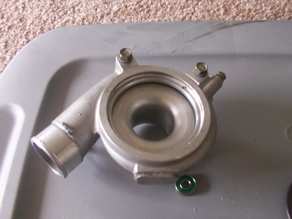
Top end of turbo -
Where the impellor rides, 1.5 mm off this housing..
And what it looks like when assembled -
Fabrication has begun and is going well, here is a part of the bracket assembly that will hold the gear/chain/motor assembly onto thr back of the tuebo, basically making it a centrifugal air pump.
And I'll be off to the machine shop soon to get all the parts I need planned out and machined.
I will, of course, keep everyone updated smile.gif
How does one control the ammount of boost pressure with this unit tho? surely it's going to be all or nothing??
No. After alot of brainstorming Ryan and I worked out a very clever, sneaky and cheap way of controlling the boost..
Ever seen a stopcock for a plumbing system? it's basically a faucet but doesnt have a tap, instead it has a red bar that you can twist to shut off the water supply.
This will be welded into an Alu intake tube and on the outlet will be fitted a small air filter. All we need to do then is turn the tap to open/close/adjust the ammount of pressure that we want to be able to come into the air system, depressureising the boost.
The concept of this is identical to a pressure cooker. on the top is a small valve that allows you to release the pressure inside..

Banned
Joined: Jun 2006
Posts: 1
Likes: 0
wow, seems like you got it all pretty much figured out..
and in theory, it seems like it will work.
how are you going to cool the system? oil? water? seems like you will need some type of cooling from that thing constantly spinning at 36000rpms. i know those ball bearings spin very freely, but it seems like it would still create some heat. and its going to have to be all PERFECTLY machined so there is no slop in the wheel, or the way the bearing is pressed in.
i wish you luck on this project, and hope to see it coming out as a success. keep us updated for sure.
Thread Starter
Senior Member
Joined: May 2007
Posts: 869
Likes: 0
Vehicle: 1998 Tiburon
We went through the whole cooling phase too socks, and came to a couple of conclusions..
1. Angle grinder motors dont need cooling. I have beaten the shit out of them before and they carry on fighting.
2. It wont be on all the time, it'll be tuned into the correct RPM on the TB housing. To get the timing right is as simple as holding the Tib @ an RPM (starting around 2k) and activating the charger with a push button. Once we find the sweet spot it'll be set up onto the throttle body to kick in and then release during the critical RPM time.
So let's say it produces a nice boost around the 2500 RPM range of the engine.. Once we have that dialed in it's just a matter of fitting a button to the TB that will let it spin up.. And, if the engine rolls off the boost at let's say 4500 RPM then we can make it so that once the TB passes that point it'll switch off.
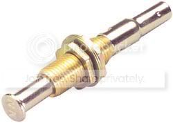
Here is a pic to demonstrate how that switch will work..Obviously I will be using a 1000w inverter to power the motor, but the switching will be done @ the 12v level to keep it safe.
That switch is adjustable, so can be moved to adjust the boost point that the SC will kick in at.
So unlike a Turbo/belt driven SC it wont be on all the time, only when I push the RPMs hard.
Rollerskate bearings are built tough. Theyre used to having my friend on them (200lbs) and with that kind of pressure they dont fail very often. Also remember there are no exhaust gases, all it'll be doing is drawing in cold air.. Bearings will be very easy to replace, and the way this is being built even in a bearing failure there is tollerance to stop the impellor hitting the housing..
I mean it wont be too hard to replace 2 bearings every 3000 miles, or expensive smile.gif The switch above is 80 cents lmao.
And then I can always fill the housing of the back end with oil and plug it up. The seals are still intact so I can fill up that body with oil and bolt the in/out lines shut.
As I say I have been studying this since last october, and any problems have been taken into serious consideration and figured out BEFORE something dangerous or catastrophic happens haha.gif
We're also going to weld some aluminum mesh into the outlet, so in the event of a failure I dont end up with impellor shrapnel in my motor haha.gif
That turbo is Mitsu, however it's a stock turbo from a WRX. And, the tech guy who fixed my rim and works @ subaru said that they dont repair turbos, so theyre constantly being replaced under warranty and thrown in the dumpster.. I will have spare parts pretty soon then lol
1. Angle grinder motors dont need cooling. I have beaten the shit out of them before and they carry on fighting.
2. It wont be on all the time, it'll be tuned into the correct RPM on the TB housing. To get the timing right is as simple as holding the Tib @ an RPM (starting around 2k) and activating the charger with a push button. Once we find the sweet spot it'll be set up onto the throttle body to kick in and then release during the critical RPM time.
So let's say it produces a nice boost around the 2500 RPM range of the engine.. Once we have that dialed in it's just a matter of fitting a button to the TB that will let it spin up.. And, if the engine rolls off the boost at let's say 4500 RPM then we can make it so that once the TB passes that point it'll switch off.
Here is a pic to demonstrate how that switch will work..Obviously I will be using a 1000w inverter to power the motor, but the switching will be done @ the 12v level to keep it safe.
That switch is adjustable, so can be moved to adjust the boost point that the SC will kick in at.
So unlike a Turbo/belt driven SC it wont be on all the time, only when I push the RPMs hard.
Rollerskate bearings are built tough. Theyre used to having my friend on them (200lbs) and with that kind of pressure they dont fail very often. Also remember there are no exhaust gases, all it'll be doing is drawing in cold air.. Bearings will be very easy to replace, and the way this is being built even in a bearing failure there is tollerance to stop the impellor hitting the housing..
I mean it wont be too hard to replace 2 bearings every 3000 miles, or expensive smile.gif The switch above is 80 cents lmao.
And then I can always fill the housing of the back end with oil and plug it up. The seals are still intact so I can fill up that body with oil and bolt the in/out lines shut.
As I say I have been studying this since last october, and any problems have been taken into serious consideration and figured out BEFORE something dangerous or catastrophic happens haha.gif
We're also going to weld some aluminum mesh into the outlet, so in the event of a failure I dont end up with impellor shrapnel in my motor haha.gif
That turbo is Mitsu, however it's a stock turbo from a WRX. And, the tech guy who fixed my rim and works @ subaru said that they dont repair turbos, so theyre constantly being replaced under warranty and thrown in the dumpster.. I will have spare parts pretty soon then lol


Moderator


Joined: Feb 2009
Posts: 11,732
Likes: 5
From: Leesville, Louisiana
Vehicle: 2001 Hyundai Tiburon
QUOTE (SOCKS @ Jun 3 2007, 01:09 PM)
wow, seems like you got it all pretty much figured out..
and in theory, it seems like it will work.
how are you going to cool the system? oil? water? seems like you will need some type of cooling from that thing constantly spinning at 36000rpms. i know those ball bearings spin very freely, but it seems like it would still create some heat. and its going to have to be all PERFECTLY machined so there is no slop in the wheel, or the way the bearing is pressed in.
i wish you luck on this project, and hope to see it coming out as a success. keep us updated for sure.
and in theory, it seems like it will work.
how are you going to cool the system? oil? water? seems like you will need some type of cooling from that thing constantly spinning at 36000rpms. i know those ball bearings spin very freely, but it seems like it would still create some heat. and its going to have to be all PERFECTLY machined so there is no slop in the wheel, or the way the bearing is pressed in.
i wish you luck on this project, and hope to see it coming out as a success. keep us updated for sure.
That shouldn't be needed. Exhaust gas is no being used. Lubrication will be needed. If this is set up so that it is used intermittantly on a switch then you can just manually lube the turbo once a week or so.
My idea would be to have a check valve bypass on it, so that it would funcion as a normal intake and let air flow freely through the system. then when you floor it, the pedal would hit a oversize lever switch.

check valve http://www.wagerusa.com/pages/marine/aircheck.html

Lever switch http://www.sps-bhv.de/53531197ee0d25b03/53...f10a/index.html
So like basically...
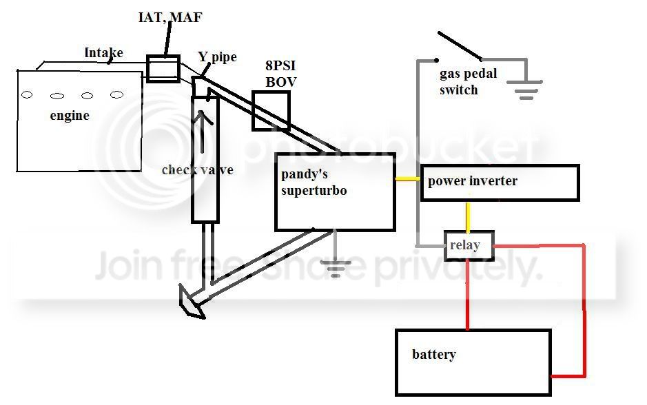
I think this could be a really squared away system!
The type of switch you suggested will have a stoping point. If you use it beware that it might bind your pedal. I suggest a lever swich off to the side because they can be mashed to the floor by extending the lever or bending it.
you can extend a lever switch with a coathanger and some epoxy. the longer the lever, the more easy to control it is. You could mount it on the firewall, near the gas pedal. When you push down the gas pedal, it hits the coathanger (which is more easily adjustable) and trigers the switch.
oh yeah, the point of the check vavle would be to reduce the resistance from the super-turbo. The blades of a turbo are ment to be spinning all the time when the car is in operation. Just to be safe i drew that in. I don't know if it's needed or not. It will allow the air to be free flowing when the superturbo is off, then when it starts to boost, the air will be trapped in the intake manifold.
I'm excited to see the outcome of this project!!! You always do the coolest custom stuff. fing02.gif
Thread Starter
Senior Member
Joined: May 2007
Posts: 869
Likes: 0
Vehicle: 1998 Tiburon
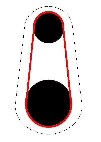
To show how the rear end of the old turbo is being built I did a tech drawing. It's not great, but shows what's needed on the rear smile.gif
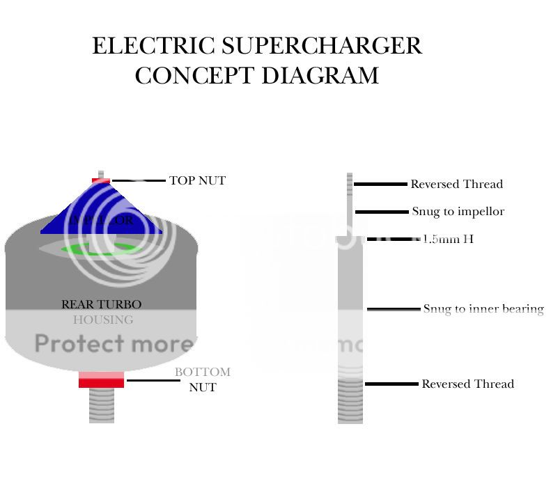
On the left is the unit itself.. Few things need esplaining there.
1. The bottom red bolt that holds it all together will not only bolt on but will also have a grub screw inside it that will lock it in place once it's adjusted. Just to make sure I dont end up with any play upward or downward on the spline.
2. As you can see from the right side pic there is a larger part of the spline that stops the impellor from moving downward and also sits in the upper bearing. So it'll go in from the front unlike before.
The trick part here though is that that stopper is also the elevation needed to put the impellor in it's position so it doesnt hit. I have gussed it roughly around the 1.5mm area, but this will all be measured using VERY precise measuring tools, to make sure that it's machined to perfection. I forget what theyre called now but theyre accurate to within 1/10th of a mm.
The thread on the rear end of the spline will allow me to bolt on the small gear that will be running from he motor on the motor assembly.. All the bearings will be greased, no indifferent to them being ran on a skateboard/skate/street luge.
But the pic is for a general idea of how the SC unit assmebly will go together, and to show I do have a plan lol smile.gif
Thread Starter
Senior Member
Joined: May 2007
Posts: 869
Likes: 0
Vehicle: 1998 Tiburon
Holy shit on a stick batman !!!
http://www.turbomagazine.com/tech/0406tur_...rger/index.html
Our completely stock Nissan Altima four-cylinder outfitted with an automatic transmission jumped from 105 whp to 184 whp with the ESC-400 at only 5 psi boost.
http://www.turbomagazine.com/tech/0406tur_...rger/index.html
Our completely stock Nissan Altima four-cylinder outfitted with an automatic transmission jumped from 105 whp to 184 whp with the ESC-400 at only 5 psi boost.

Senior Member
Joined: Sep 2002
Posts: 2,236
Likes: 0
thomas knight sells an electric supercharger that does in deed create actual boost. problem is it involves adding like 4 batteries to your car, and can only be used in 10 sec bursts. and i think it was like 6k.