
Some Little Upgrade...

Thread Starter
Senior Member

Joined: Jul 2004
Posts: 112
Likes: 0
From: Ravenna / ITALY
ok...
a little neon upgrade, hidden under the seats, beacause i love the lights but i hate see the neon tubes smile.gif

thanks to the chromed carpets, the lights is 3 times stronger...
on the front too:

but now, it's a long time that i'm working on few thngs but i'm hesitating because i don't know where is the right place to put them..
1) 21 leds RPM gauge

.... circuit DONE and TESTED... wire on the instrum. cluster found (need only join the rpm signal wire.. but i'm afraid of unmount the entire instrument cluster )
)
.. i was guessing to drill holes (a definitive mod!) to put the led like this:

2) Gear Display (with green/red switch)
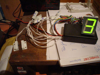
the display is rally style, and i choose a big one 44mm*33mm
i used magnetic contacts.. not dip-switches.. so you only need to get close to the magnetes for *closing* the circuit and let the display shows you the right number... no more broken switch after long use of "clicks" ..
i was thinking to join this disaplay with a DIY 10 led air/fuel meter
i'm finishing the circuit of the air/fuel meter.. leds are already preapared (with RRR-BBBBB-WW combination of leds Red/Blue/White)
help with how you think to join these two circuit together or where is the ideal place to put them
don't say the right mount because i already placed 3 gauge

ok. any helps/advice are welcome smile.gif
CIAO!
a little neon upgrade, hidden under the seats, beacause i love the lights but i hate see the neon tubes smile.gif
thanks to the chromed carpets, the lights is 3 times stronger...
on the front too:
but now, it's a long time that i'm working on few thngs but i'm hesitating because i don't know where is the right place to put them..
1) 21 leds RPM gauge
.... circuit DONE and TESTED... wire on the instrum. cluster found (need only join the rpm signal wire.. but i'm afraid of unmount the entire instrument cluster
).. i was guessing to drill holes (a definitive mod!) to put the led like this:
2) Gear Display (with green/red switch)
the display is rally style, and i choose a big one 44mm*33mm
i used magnetic contacts.. not dip-switches.. so you only need to get close to the magnetes for *closing* the circuit and let the display shows you the right number... no more broken switch after long use of "clicks" ..
i was thinking to join this disaplay with a DIY 10 led air/fuel meter
i'm finishing the circuit of the air/fuel meter.. leds are already preapared (with RRR-BBBBB-WW combination of leds Red/Blue/White)
help with how you think to join these two circuit together or where is the ideal place to put them
don't say the right mount because i already placed 3 gauge
ok. any helps/advice are welcome smile.gif
CIAO!


Senior Member
Joined: Oct 2003
Posts: 3,832
Likes: 0
From: Fort Erie, Ontario
Vehicle: 2004 Acura TL
QUOTE (Mr_Hyde_NT @ May 15 2005, 11:00 AM)
.... circuit DONE and TESTED... wire on the instrum. cluster found (need only join the rpm signal wire.. but i'm afraid of unmount the entire instrument cluster )
.. i was guessing to drill holes (a definitive mod!) to put the led like this:
).. i was guessing to drill holes (a definitive mod!) to put the led like this:
I was going to do the same thing Hyde. Except I was going to use it as an A/F gauge insted. That looks cool, I'm glad you chopped it first. I think it's a great idea.
All of your ideas are actually.

Senior Member
Joined: Apr 2005
Posts: 216
Likes: 0
From: darmstadt germany
yeah i think i'd pay for a gear display too. they're so f***in hot!!! i'll feel like i'm faster but i won't be.... kinda rice but real nice lol. lemme know man, all of your work looks well thought out and has quality, i'm impressed by those lights you got


Senior Member
Joined: Sep 2009
Posts: 4,185
Likes: 0
Vehicle: Elantra HD / 2007
Man, it looks hot!
I think it would be better to use different color shift lights LEDs. Cause it would be much easier to know what RPM is by LED color (not by numbers of LEDs on).
For example you can put:
green LEDs (3000-4000 RPM)
yellow LEDs (4000-5500)
red LEDs (5500-6500)
Do you have circuit diagram for gear indicator?
What about shifting lights?


Senior Member
Joined: May 2004
Posts: 2,214
Likes: 0
From: Bel Air, MD
They all look nice but the gear and rpm thing are a little worthless IMO. Kinda like getting a second tach. If you want something to tell you when to shift get a shift light and a pill module.