
Diy: Alternator Bearings Removal & Replacement

Thread Starter
Super Moderator


Joined: Sep 2001
Posts: 10,795
Likes: 5
From: Pflugerville, TX
Vehicle: 2000 Elantra
This DIY will show you the process of removing/replacing bearings in a stock MANDO 90-amp alternator for a 96-00 Elantra or 97-01 Tiburon. Other manufacturers' alternators will be similar.
The parts (bearings) can be found at any GOOD bearing supply house, or a local alternator shop. The dealer can get as close as a whole alternator; they don't sell parts for them, they sell whole remanufactured units. You will probably have to talk to a local alternator shop to get any of the other alternator parts.
Tools you will need:
8mm, 10mm, 12mm socket wrenches
#2 philips screwdriver
24mm socket for the pulley nut and either a bench vise or an impact wrench to get the nut on and off
Rubber Mallet (NOT a metal hammer! )
Soldering iron (recommended, optional)
Fine (600+ grit) sandpaper (optional)
AA size battery (optional)
Isopropyl alcohol (optional)
Multimeter (optional)
BIG bench vise, or hydraulic press, or local alternator shop (see text)
Parts you will need:
Suitable size 6303 and 6202 bearings (see text)
Preliminary step: Remove the alternator. My DIY for that is here: Alternator Removal & Replacement DIY
(Still not on the approved DIY list, for unknown reasons)
You don't have to fool with any wires or connectors, but there is a little soldering involved.
I don't recommend beer when working on stuff required to make your car drivable, but to each his own.
I was getting frustrated toward the end, so the reassembly stuff doesn't have pictures. It all looks the same anyway as reassembly is the opposite of disassembly. I had never done this before, so I took notes and pictures as I went. Real alternator mechanics, feel free to chime in if I missed something or did something stupid.
*******
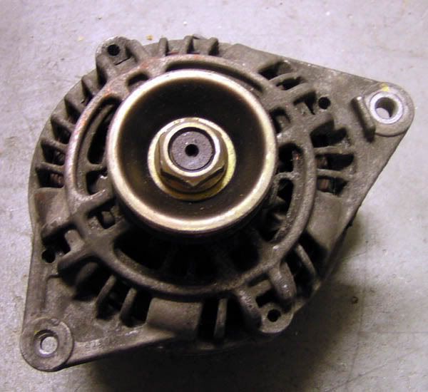
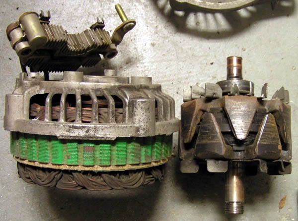
Here is our unfortunate victim: a standard OEM 90 amp alternator for a 96-00 Elantra or 97-01 Tiburon. It was pulled from a running car. Spinning the pulley resulted in a very long spin-down, with lots of noise. Diagnosis: bad bearings.
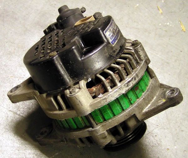
The front is the pulley end. The back is the end with the black cover.
The most obvious thing to do seemed to be to split the front and back halves apart. There are four long screws holding the cases together. . . aaaand the screws are not all accessible.
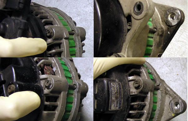
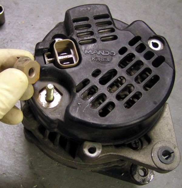
So we have to get the back cover off. Here is your reference shot:
There are two screws
A note about ALL the screws on this thing: they are nastied in place. PUSH VERY HARD and turn FIRMLY with the screwdriver. You do NOT want to strip out the heads of these screws. If you do, you'll need a dremel cut-off wheel to make them into flat-head screws; not very fun.
The battery post has a 12 and a 10mm nut, as well as a plastic guard we have to get off. First, take off the bracket that holds the cables from the car's wiring harness, if it is still attached (yours may still be on your car).
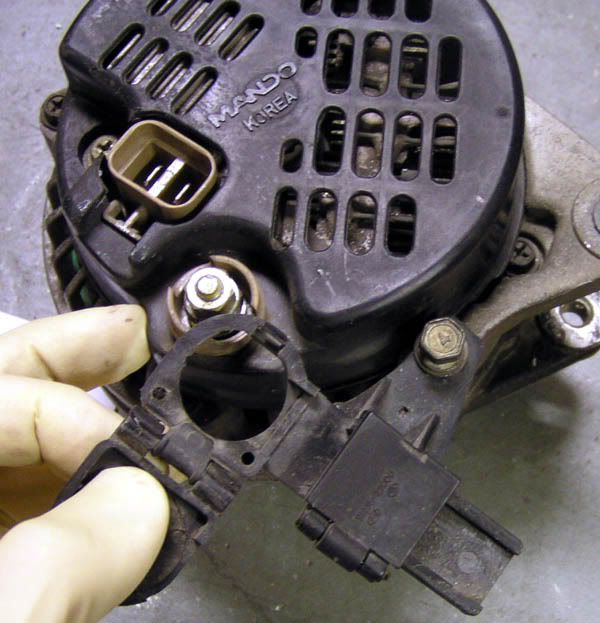
Then pull the nuts and the guard
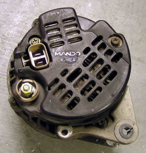
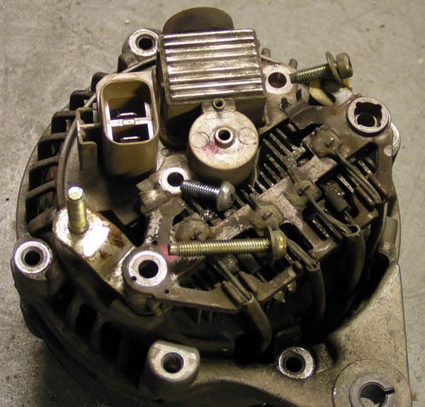
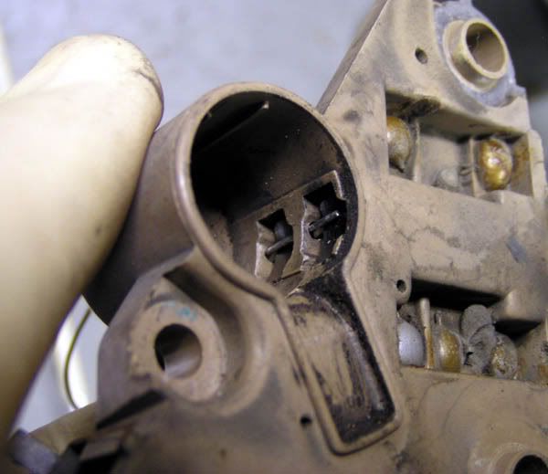
The plastic rear cover is now free, and it should pop right off. You are looking at, clockwise from the left:
Two-pronged voltage sensing and lamp connector
Voltage Regulator heat sink
The bit with wires going from lower-right to upper-left, from inside the alternator, is the diode assembly
The big post is the + voltage charging post to where the battery cable connects
The round bit in the middle is the housing for the commutator/sliprings & brushes
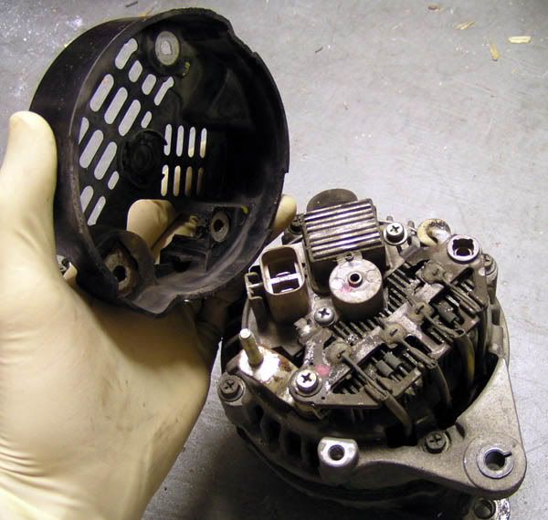
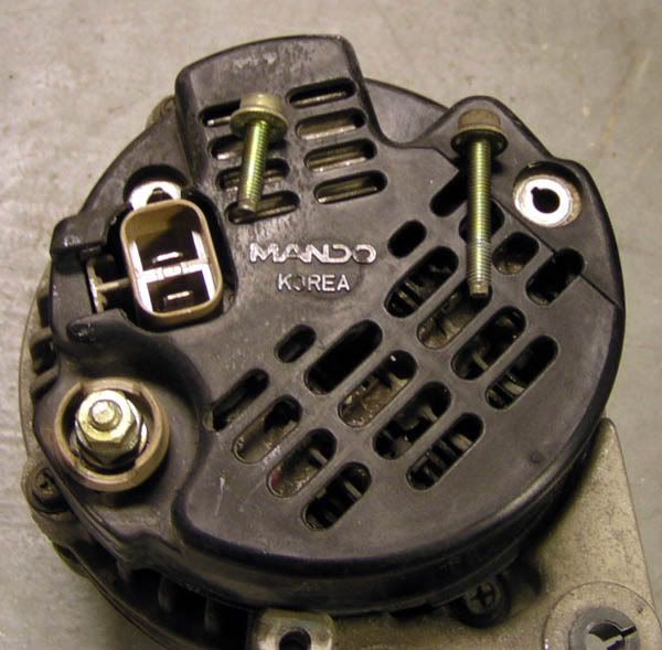
Now we can get at the four long screws. They are 8mm headed bolts with philips crosses cut into them. Crack them loose with a wrench and pull them with the screwdriver. They are all the same. Notice as you pull them out, they all sit in one of the grooves in the stator housing. This will help you when you go to reassemble the alternator. For now, just take note of this feature for future reference.
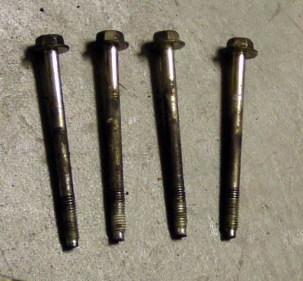
BEFORE you split the cases, make a witness mark on the case with a scribe or a knife, so it scratches the metal deeply. Trust me you will be glad you did this later when you go to marry the cases again.
Another thing to<span style="color:#FF0000"> be careful </span>of BEFORE you split the cases, is the sliprings and brushes. If you scratch the sliprings on the side of the case as you take it all apart, you will need a new rotor. Be CAREFUL of the sliprings.
At this point, I was stuck. I didn't have an impact gun and it sure looked like I needed to have one. As it turns out, it should be possible to separate the cases with the pulley on but I didn't know how at the time. Hyundaitechinfo.com says to heat the rear bearing area of the rear case with a 200W soldering gun. Do NOT use a heat gun, as it may damage the diode assembly. There is a lock ring in there, and heating the case is supposed to make the halves of the alternator easier to disassemble. HMA says to use screwdrivers to pry the case apart, but I used a mallet and some tappa tappa tappa action. Either way, the nut is 24mm
Then you can put the rotor in a vise (Squeeze gently! don't squish it!) and remove the nut.
(image from hyundaitechinfo.com)
I borrowed an impact wrench.
Crank the impact gun air supply all the way up. 80PSI just spun the pulley in my strap wrench. 120PSI got it free.
There is a spacer behind the pulley. The raised circle in the middle of the pulley faces the spacer. The flat side of the pulley faces out, towards the nut.
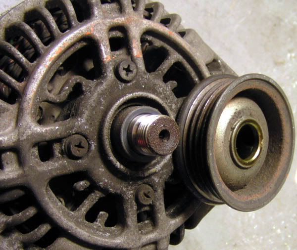
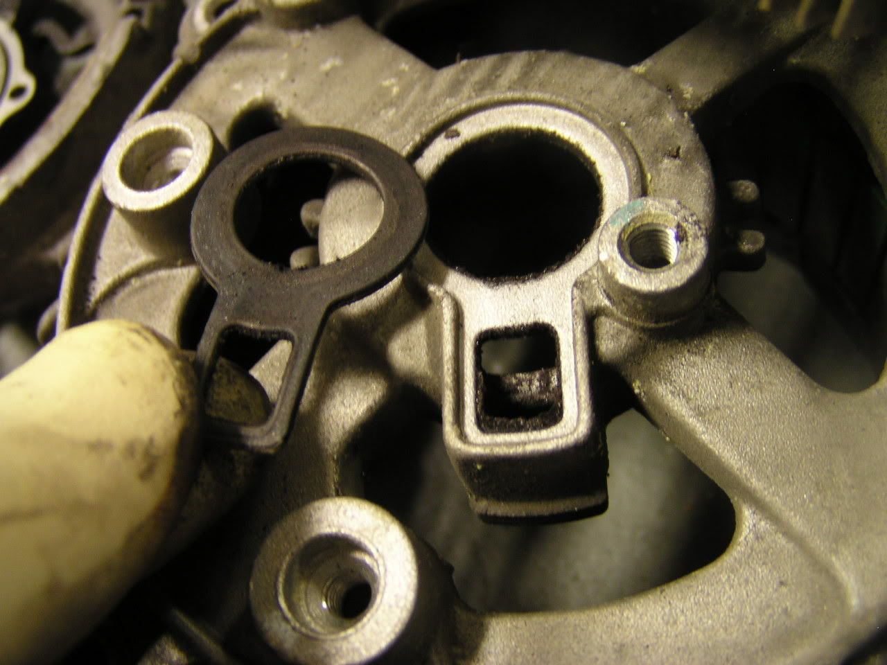
This was the point at which I split the cases. The front case came off, leaving the rotor in the rear case. Behind the front case, there is a bearing. It is pressed into the case with very little pressure, and retained with a square plate. Behind the plate, between the rotor and the bearing, is another spacer. This one is thinner, with a larger diameter. Don't mix them up when you go to reassemble the alternator.
Spacer behind the bearing:
Spacers: NOT the same!
Split the cases. Pull the screws and the plate.
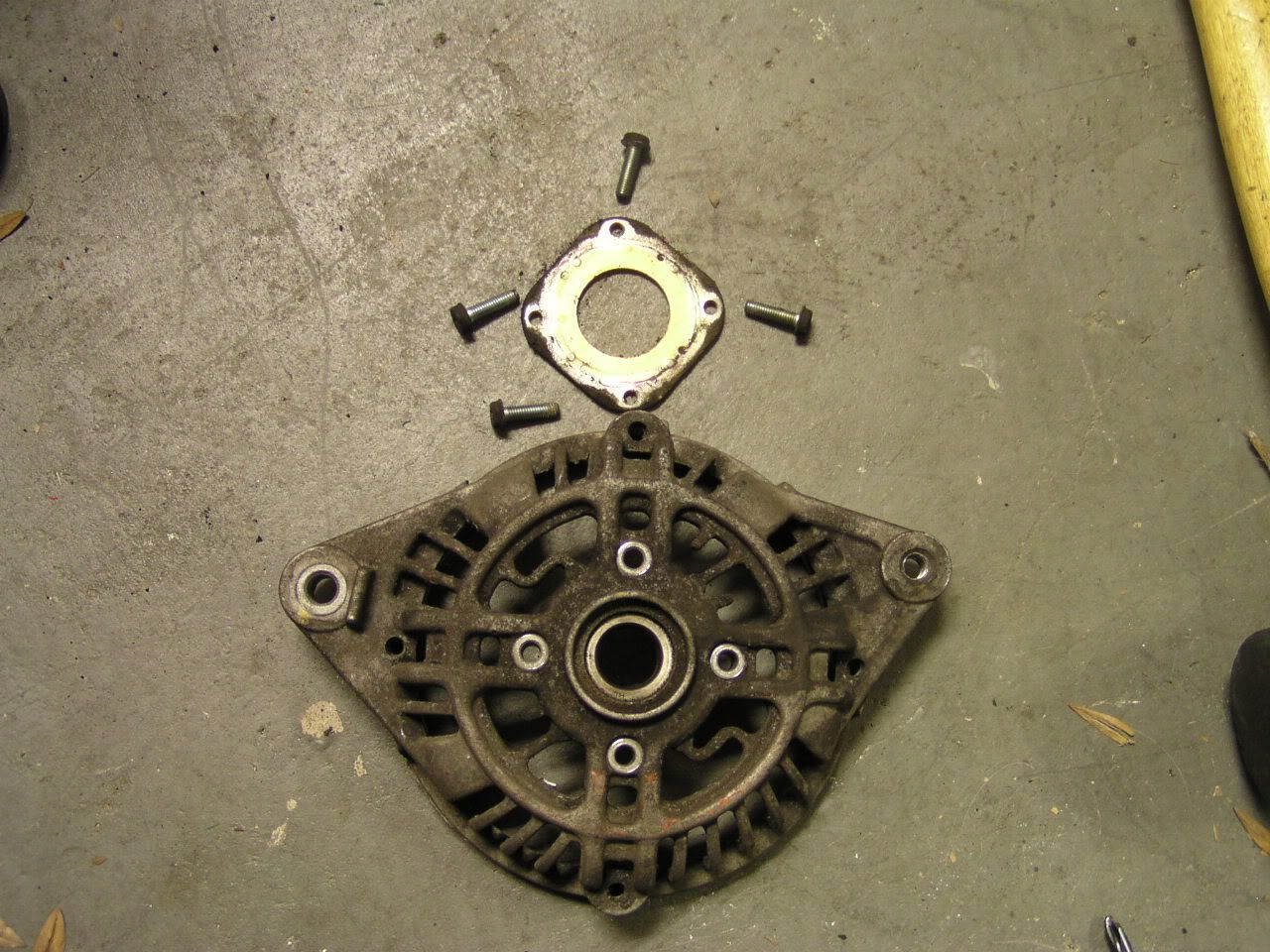
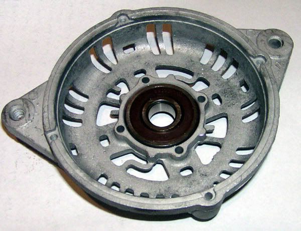
The front bearing is now exposed.
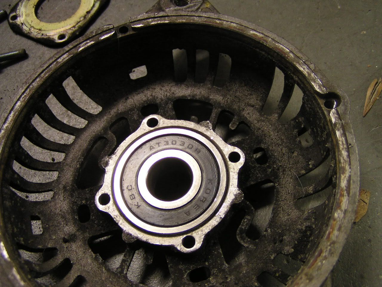
I used a mallet hitting a socket, to drive the old front bearing out. It would be no sweat at all for even the smallest press to push this thing out, and if you could rig it up right, a 6" bench vise would probably be more than enough power. I hit it with penetrating oil beforehand but I am pretty sure that was not necessary.
The rotor was now pretty floppy in the rear case, because the rear bearing was all loosey-goosey (bad). I guess this is when I was supposed to heat the rear bearing area with the soldering gun, but I just gave it a tappa-tappa with my mallet on the end of the sliprings. But we're jumping ahead again.
To get to the sliprings, you need to take the back side electronics apart. There are three philips screws holding it all together.
Unsolder the regulator from the diode assembly; there was one solder joint on my alternator but yours may have two.
Gently pull the regulator/brush holder assembly off the sliprings. Take extreme care not to damage the sliprings.
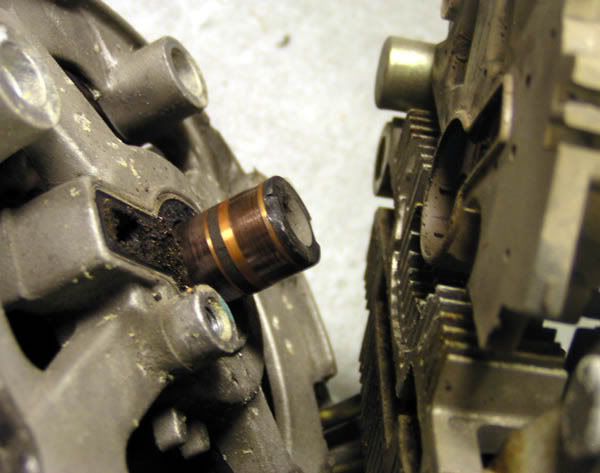
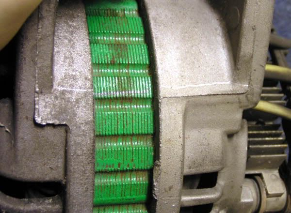
Look how crappy it is in there, with all the worn-down brush material.
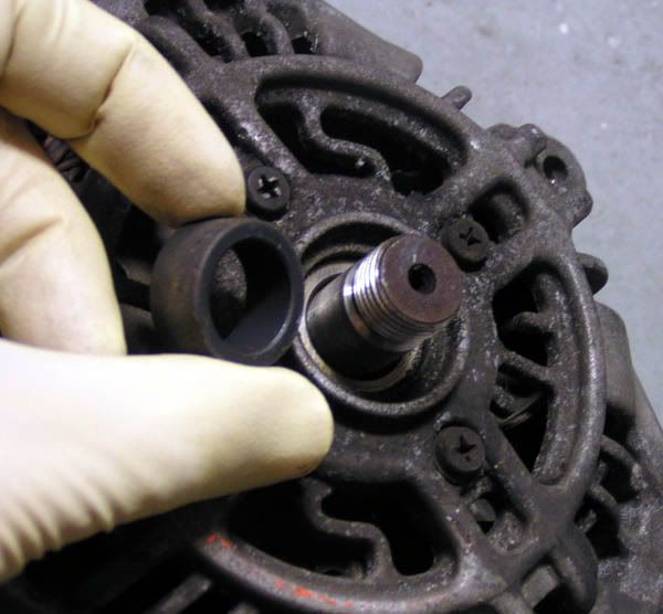
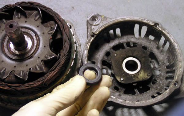
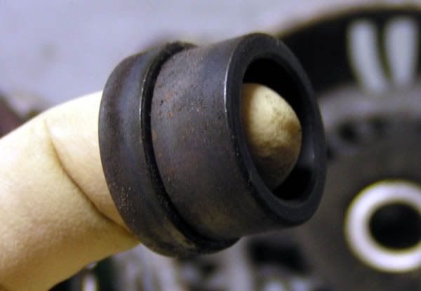
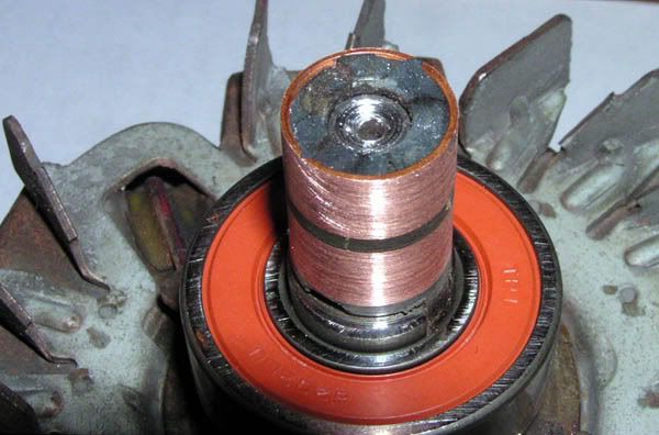
Pull the rubber seal off the sliprings.
Here are your brushes. All the gunk in the groove to the upper-right used to be part of the brushes. It's also in the corners of the brushes housing. Clean all this out while you're in there.
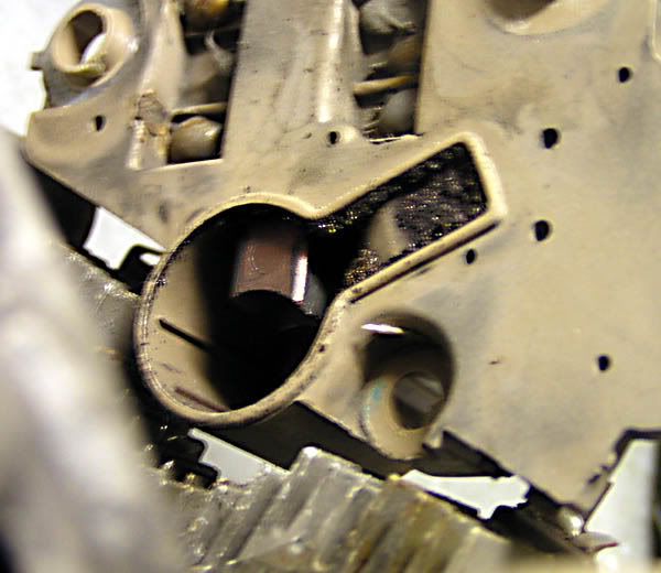
If your brushes are too far worn, they or the whole regulator will need replacement. Fortunately for me, these have plenty of life left in 'em.
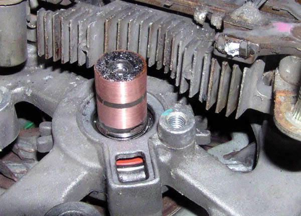
Heat the case now, and tap out the rotor. The bearing has a little round metal bit I presume is the lock ring on it, as well as a lot more trash from the brushes.
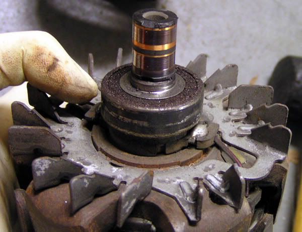
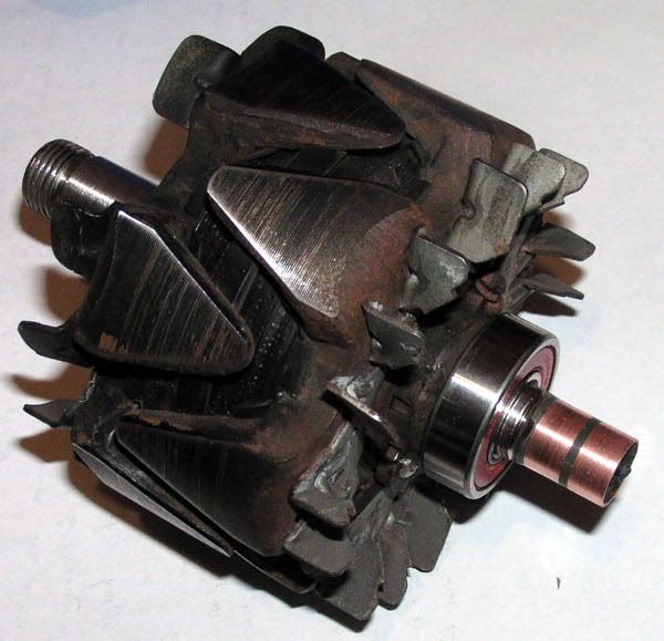
Here is what you will be looking at when the rotor finally comes out:
The commutator end bearing was toast. The front bearing was a bit loose and crunchy but it still ran true. The rear bearing I could wiggle with my fingers, side to side. Completely shot. I pulled the little metal ring off -gently, it bends easily- but I couldn't pull the bearing itself. This bearing was VERY tight on the rotor. I tried a little 2-jaw puller and it was bending the jaws. This was the point at which I gave up and called on the professionals.
We stopped in at Texas Alternator Starter Service in Austin and they took about 15 minutes, and charged $20, to replace the rear bearing, turn the sliprings down so they were flat again (the dark rings are slightly worn-in spots in the copper), cleaned the front housing, and pressed in a new bearing to the front housing. They cleaned the surface smutz off the front spindle of the rotor as well.
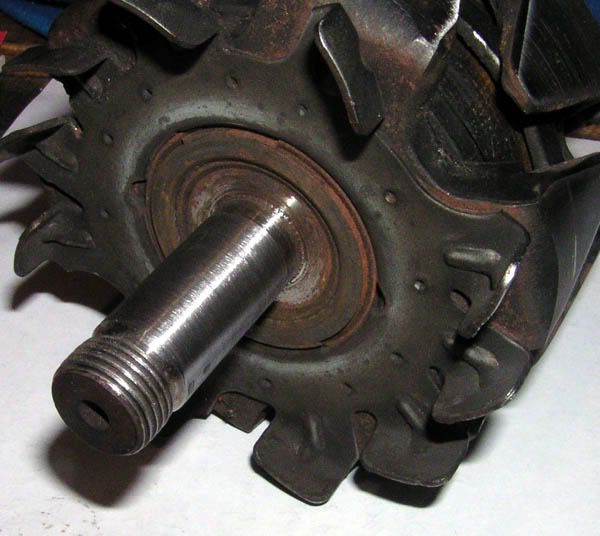
They also did me the favor of smashing off the plastic end of the sliprings. mad.gif
It seemed like a good idea at the time, so I put some epoxy on the end of the sliprings. I didn't think the copper would be walking away, but I didn't much like the idea of it being possible.
The big question I had is: what size bearings are these? The work order said 6303 and 6202, and the invoice said 6-303-4 and 6-202-4. The old bearings were marked AT303DR and 6202LHI which I couldn't find online. The new bearings they installed are a WBD 6303D and a TPI 6202LU. In the future, I am going to go to the local bearing supply house in P'ville and get a set of top-quality, made-in-USA, sealed and lubricated-for-life, high speed, high temp rated bearings. The cheap foreign ones have been my bane for a decade. For now, these will serve and I now know what sizes to get.
You could use a small press or a large vise to install the front bearing. The rear will need to be pressed on, taking great care not to damage the sliprings. However they get there, the new bearings are installed.
Replace the metal lock ring on the rear bearing end and fit the rotor to the rear housing. Be careful not to mar the slipring surface on the rear housing!
I deburred the front bearing plate a little, and reinstalled the plate over the front bearing.
Be sure you put the spacers back in their proper places!
Fit the cases back together. This is where you will be glad of the line you scored, earlier. Without that line, it is easy to get confused which way the housings mate back together.
Screw in the four big screws and do not over-tighten them. Replace the pulley nut.
Refit the rubber commutator end seal
Push the brushes all the way in to their housing with a wooden or soft plastic tool, and insert a wire or pin to hold them back in the housing.
Screw down the rectifier assembly
Screw down the voltage regulator/brush holder assembly, and solder the regulator to the diode assembly.
Pull the pin to release the brushes.
Refit the plastic rear case
You're done! fing02.gif
When everything is all back together and correctly assembled, there should be NO play along the axis of the rotor, and NO play side-to-side on ANYTHING. The rotor should spin smoothly, but it should be like the ends are in molasses or heavy grease (because the bearings are greased). You should be able to count on both hands the number of seconds the rotor spins, when you give the pulley a whirl by hand. It should NOT just spin and spin and spin, and it should NOT make ANY noise, aside from very, very, very quiet normal bearing noises. If you are next to an appliance of any kind or a fan or a radio, you should not hear the new bearings turning. You should not feel any "crunchy" sensation when you turn the pulley.
Go to the local non-Autozone major chain auto parts store and they will test your alternator for you, free. Do this BEFORE you fit it on your car.
********
Other notes:
You should have about 2.7 ohms between the sliprings (measured directly on the copper rings) and they should not have any electrical contact with the rotor. The field coil housing (the part with all the thick metal triangles) should be short to ground (the metal end of the rotor). If these checks fail, you need a new rotor.
You need continuity between the stator coil leads, and there should be no continuity between the coils and the core of the stator. If the coils are open or grounded, you need a new stator.
The three small diodes should each measure continuity only in one direction. These are a hassle to replace, but they can be replaced.
The positive rectifier and stator coil lead connection terminal should read continuity in only one direction.
image from hyundaitechinfo.com
The negative rectifier and stator coil lead connection terminal should read continuity in only one direction.
image from hyundaitechinfo.com
If the diode checks fail, the diodes or diode assembly need to be replaced.
********
The aftermath, and additional steps:
Sorry no photos for this part. If you get this far, you'll see what I'm talking about. If not, count yourself fortunate.
When I first reassembled this alternator and the man at Advance Auto Parts tested it, he said it was giving all of 2 Volts (vice 13-14V). I knew it had been working when I took it apart, because it came from a running car. That eliminated the coils and regulator, leaving only the slip rings and brushes as likely points of failure. I took the regulator off and had a second look at the brushes and sliprings. They were a bit dirty, and the brushes were a little chewed up from me pushing on them with tools harder than the material the brushes are made of, to poke them into their housings. Great. owned.gif
The black plastic boot on the regulator housing is a cover over the end of the brushes' wires. Pull that off. The brushes' wires are soldered in place and spring-loaded to push against the slip rings. There is a thick braided copper cable from each brush that pokes through the length of a coil spring, and out through the cap on the end of the brush housing. Then the braid is wound around and soldered to a terminal of the regulator. I used a solder wick to remove the solder from the braid and terminal, and found that the end of the housing would not come off. The terminals are twisted to hold the cap in place. Bend them straight with pliers and tug gently and the cap should come off. Tug too hard and you WILL break the plastic separator between the two wires. Be careful; remember the cap is spring-loaded. The cap and springs will all want to go flying away.
Take a knife tip or a scribe and mark on the bottom of the regulator housing, the orientation of the brushes. They poke out more on one side than the other and only go back in properly one way. Remove the brushes.
I measured the outside diameter of the sliprings and found them almost exactly the same diameter of a "AA" size battery. I wrapped some 600 grit sandpaper on a battery and redressed the face of the brushes until they were smooth. Then I got a bunch of paper towels and some isopropyl alcohol and scrubbed the face of the brushes until they stopped making the towels come away gray. This took a surprisingly long time. Pull the wire on each brush straight, and poke the wire through its spring. Poke the end of the wire through the appropriate hole in the end cap. The springs will pull the brushes sideways, but that's ok. The easy thing to do with this part for now, is tack the ends of the braids together with solder so they hold each other and the springs won't pull the wires back thru the cap.
If the slip rings are smooth, just clean them off with the alcohol. If not, hit them with the sandpaper and then clean them off.
Reinsert the sliprings into their housings. The terminals for the regulator will slip into their holes in the end cap.
Desolder the braid wires from each other and solder them to the appropriate voltage regulator terminal. There is a divider, so they are pretty hard to get mixed up as to which wire goes to which terminal.
Verify approx. 2.7 ohms between the wires. That's good contact. Reassemble the alternator and have it tested. If that was your problem (it was mine) the alternator is now ready to install. Install it and test the output voltage.
NOW is the time for the frosty beverage of your choice. fing02.gif
The parts (bearings) can be found at any GOOD bearing supply house, or a local alternator shop. The dealer can get as close as a whole alternator; they don't sell parts for them, they sell whole remanufactured units. You will probably have to talk to a local alternator shop to get any of the other alternator parts.
Tools you will need:
8mm, 10mm, 12mm socket wrenches
#2 philips screwdriver
24mm socket for the pulley nut and either a bench vise or an impact wrench to get the nut on and off
Rubber Mallet (NOT a metal hammer! )
Soldering iron (recommended, optional)
Fine (600+ grit) sandpaper (optional)
AA size battery (optional)
Isopropyl alcohol (optional)
Multimeter (optional)
BIG bench vise, or hydraulic press, or local alternator shop (see text)
Parts you will need:
Suitable size 6303 and 6202 bearings (see text)
Preliminary step: Remove the alternator. My DIY for that is here: Alternator Removal & Replacement DIY
(Still not on the approved DIY list, for unknown reasons)
You don't have to fool with any wires or connectors, but there is a little soldering involved.
I don't recommend beer when working on stuff required to make your car drivable, but to each his own.
I was getting frustrated toward the end, so the reassembly stuff doesn't have pictures. It all looks the same anyway as reassembly is the opposite of disassembly. I had never done this before, so I took notes and pictures as I went. Real alternator mechanics, feel free to chime in if I missed something or did something stupid.
*******
Here is our unfortunate victim: a standard OEM 90 amp alternator for a 96-00 Elantra or 97-01 Tiburon. It was pulled from a running car. Spinning the pulley resulted in a very long spin-down, with lots of noise. Diagnosis: bad bearings.
The front is the pulley end. The back is the end with the black cover.
The most obvious thing to do seemed to be to split the front and back halves apart. There are four long screws holding the cases together. . . aaaand the screws are not all accessible.
So we have to get the back cover off. Here is your reference shot:
There are two screws
A note about ALL the screws on this thing: they are nastied in place. PUSH VERY HARD and turn FIRMLY with the screwdriver. You do NOT want to strip out the heads of these screws. If you do, you'll need a dremel cut-off wheel to make them into flat-head screws; not very fun.
The battery post has a 12 and a 10mm nut, as well as a plastic guard we have to get off. First, take off the bracket that holds the cables from the car's wiring harness, if it is still attached (yours may still be on your car).
Then pull the nuts and the guard
The plastic rear cover is now free, and it should pop right off. You are looking at, clockwise from the left:
Two-pronged voltage sensing and lamp connector
Voltage Regulator heat sink
The bit with wires going from lower-right to upper-left, from inside the alternator, is the diode assembly
The big post is the + voltage charging post to where the battery cable connects
The round bit in the middle is the housing for the commutator/sliprings & brushes
Now we can get at the four long screws. They are 8mm headed bolts with philips crosses cut into them. Crack them loose with a wrench and pull them with the screwdriver. They are all the same. Notice as you pull them out, they all sit in one of the grooves in the stator housing. This will help you when you go to reassemble the alternator. For now, just take note of this feature for future reference.
BEFORE you split the cases, make a witness mark on the case with a scribe or a knife, so it scratches the metal deeply. Trust me you will be glad you did this later when you go to marry the cases again.
Another thing to<span style="color:#FF0000"> be careful </span>of BEFORE you split the cases, is the sliprings and brushes. If you scratch the sliprings on the side of the case as you take it all apart, you will need a new rotor. Be CAREFUL of the sliprings.
At this point, I was stuck. I didn't have an impact gun and it sure looked like I needed to have one. As it turns out, it should be possible to separate the cases with the pulley on but I didn't know how at the time. Hyundaitechinfo.com says to heat the rear bearing area of the rear case with a 200W soldering gun. Do NOT use a heat gun, as it may damage the diode assembly. There is a lock ring in there, and heating the case is supposed to make the halves of the alternator easier to disassemble. HMA says to use screwdrivers to pry the case apart, but I used a mallet and some tappa tappa tappa action. Either way, the nut is 24mm
Then you can put the rotor in a vise (Squeeze gently! don't squish it!) and remove the nut.
(image from hyundaitechinfo.com)
I borrowed an impact wrench.
Crank the impact gun air supply all the way up. 80PSI just spun the pulley in my strap wrench. 120PSI got it free.
There is a spacer behind the pulley. The raised circle in the middle of the pulley faces the spacer. The flat side of the pulley faces out, towards the nut.
This was the point at which I split the cases. The front case came off, leaving the rotor in the rear case. Behind the front case, there is a bearing. It is pressed into the case with very little pressure, and retained with a square plate. Behind the plate, between the rotor and the bearing, is another spacer. This one is thinner, with a larger diameter. Don't mix them up when you go to reassemble the alternator.
Spacer behind the bearing:
Spacers: NOT the same!
Split the cases. Pull the screws and the plate.
The front bearing is now exposed.
I used a mallet hitting a socket, to drive the old front bearing out. It would be no sweat at all for even the smallest press to push this thing out, and if you could rig it up right, a 6" bench vise would probably be more than enough power. I hit it with penetrating oil beforehand but I am pretty sure that was not necessary.
The rotor was now pretty floppy in the rear case, because the rear bearing was all loosey-goosey (bad). I guess this is when I was supposed to heat the rear bearing area with the soldering gun, but I just gave it a tappa-tappa with my mallet on the end of the sliprings. But we're jumping ahead again.
To get to the sliprings, you need to take the back side electronics apart. There are three philips screws holding it all together.
Unsolder the regulator from the diode assembly; there was one solder joint on my alternator but yours may have two.
Gently pull the regulator/brush holder assembly off the sliprings. Take extreme care not to damage the sliprings.
Look how crappy it is in there, with all the worn-down brush material.
Pull the rubber seal off the sliprings.
Here are your brushes. All the gunk in the groove to the upper-right used to be part of the brushes. It's also in the corners of the brushes housing. Clean all this out while you're in there.
If your brushes are too far worn, they or the whole regulator will need replacement. Fortunately for me, these have plenty of life left in 'em.
Heat the case now, and tap out the rotor. The bearing has a little round metal bit I presume is the lock ring on it, as well as a lot more trash from the brushes.
Here is what you will be looking at when the rotor finally comes out:
The commutator end bearing was toast. The front bearing was a bit loose and crunchy but it still ran true. The rear bearing I could wiggle with my fingers, side to side. Completely shot. I pulled the little metal ring off -gently, it bends easily- but I couldn't pull the bearing itself. This bearing was VERY tight on the rotor. I tried a little 2-jaw puller and it was bending the jaws. This was the point at which I gave up and called on the professionals.
We stopped in at Texas Alternator Starter Service in Austin and they took about 15 minutes, and charged $20, to replace the rear bearing, turn the sliprings down so they were flat again (the dark rings are slightly worn-in spots in the copper), cleaned the front housing, and pressed in a new bearing to the front housing. They cleaned the surface smutz off the front spindle of the rotor as well.
They also did me the favor of smashing off the plastic end of the sliprings. mad.gif
It seemed like a good idea at the time, so I put some epoxy on the end of the sliprings. I didn't think the copper would be walking away, but I didn't much like the idea of it being possible.
The big question I had is: what size bearings are these? The work order said 6303 and 6202, and the invoice said 6-303-4 and 6-202-4. The old bearings were marked AT303DR and 6202LHI which I couldn't find online. The new bearings they installed are a WBD 6303D and a TPI 6202LU. In the future, I am going to go to the local bearing supply house in P'ville and get a set of top-quality, made-in-USA, sealed and lubricated-for-life, high speed, high temp rated bearings. The cheap foreign ones have been my bane for a decade. For now, these will serve and I now know what sizes to get.
You could use a small press or a large vise to install the front bearing. The rear will need to be pressed on, taking great care not to damage the sliprings. However they get there, the new bearings are installed.
Replace the metal lock ring on the rear bearing end and fit the rotor to the rear housing. Be careful not to mar the slipring surface on the rear housing!
I deburred the front bearing plate a little, and reinstalled the plate over the front bearing.
Be sure you put the spacers back in their proper places!
Fit the cases back together. This is where you will be glad of the line you scored, earlier. Without that line, it is easy to get confused which way the housings mate back together.
Screw in the four big screws and do not over-tighten them. Replace the pulley nut.
Refit the rubber commutator end seal
Push the brushes all the way in to their housing with a wooden or soft plastic tool, and insert a wire or pin to hold them back in the housing.
Screw down the rectifier assembly
Screw down the voltage regulator/brush holder assembly, and solder the regulator to the diode assembly.
Pull the pin to release the brushes.
Refit the plastic rear case
You're done! fing02.gif
When everything is all back together and correctly assembled, there should be NO play along the axis of the rotor, and NO play side-to-side on ANYTHING. The rotor should spin smoothly, but it should be like the ends are in molasses or heavy grease (because the bearings are greased). You should be able to count on both hands the number of seconds the rotor spins, when you give the pulley a whirl by hand. It should NOT just spin and spin and spin, and it should NOT make ANY noise, aside from very, very, very quiet normal bearing noises. If you are next to an appliance of any kind or a fan or a radio, you should not hear the new bearings turning. You should not feel any "crunchy" sensation when you turn the pulley.
Go to the local non-Autozone major chain auto parts store and they will test your alternator for you, free. Do this BEFORE you fit it on your car.
********
Other notes:
You should have about 2.7 ohms between the sliprings (measured directly on the copper rings) and they should not have any electrical contact with the rotor. The field coil housing (the part with all the thick metal triangles) should be short to ground (the metal end of the rotor). If these checks fail, you need a new rotor.
You need continuity between the stator coil leads, and there should be no continuity between the coils and the core of the stator. If the coils are open or grounded, you need a new stator.
The three small diodes should each measure continuity only in one direction. These are a hassle to replace, but they can be replaced.
The positive rectifier and stator coil lead connection terminal should read continuity in only one direction.
image from hyundaitechinfo.com
The negative rectifier and stator coil lead connection terminal should read continuity in only one direction.
image from hyundaitechinfo.com
If the diode checks fail, the diodes or diode assembly need to be replaced.
********
The aftermath, and additional steps:
Sorry no photos for this part. If you get this far, you'll see what I'm talking about. If not, count yourself fortunate.
When I first reassembled this alternator and the man at Advance Auto Parts tested it, he said it was giving all of 2 Volts (vice 13-14V). I knew it had been working when I took it apart, because it came from a running car. That eliminated the coils and regulator, leaving only the slip rings and brushes as likely points of failure. I took the regulator off and had a second look at the brushes and sliprings. They were a bit dirty, and the brushes were a little chewed up from me pushing on them with tools harder than the material the brushes are made of, to poke them into their housings. Great. owned.gif
The black plastic boot on the regulator housing is a cover over the end of the brushes' wires. Pull that off. The brushes' wires are soldered in place and spring-loaded to push against the slip rings. There is a thick braided copper cable from each brush that pokes through the length of a coil spring, and out through the cap on the end of the brush housing. Then the braid is wound around and soldered to a terminal of the regulator. I used a solder wick to remove the solder from the braid and terminal, and found that the end of the housing would not come off. The terminals are twisted to hold the cap in place. Bend them straight with pliers and tug gently and the cap should come off. Tug too hard and you WILL break the plastic separator between the two wires. Be careful; remember the cap is spring-loaded. The cap and springs will all want to go flying away.
Take a knife tip or a scribe and mark on the bottom of the regulator housing, the orientation of the brushes. They poke out more on one side than the other and only go back in properly one way. Remove the brushes.
I measured the outside diameter of the sliprings and found them almost exactly the same diameter of a "AA" size battery. I wrapped some 600 grit sandpaper on a battery and redressed the face of the brushes until they were smooth. Then I got a bunch of paper towels and some isopropyl alcohol and scrubbed the face of the brushes until they stopped making the towels come away gray. This took a surprisingly long time. Pull the wire on each brush straight, and poke the wire through its spring. Poke the end of the wire through the appropriate hole in the end cap. The springs will pull the brushes sideways, but that's ok. The easy thing to do with this part for now, is tack the ends of the braids together with solder so they hold each other and the springs won't pull the wires back thru the cap.
If the slip rings are smooth, just clean them off with the alcohol. If not, hit them with the sandpaper and then clean them off.
Reinsert the sliprings into their housings. The terminals for the regulator will slip into their holes in the end cap.
Desolder the braid wires from each other and solder them to the appropriate voltage regulator terminal. There is a divider, so they are pretty hard to get mixed up as to which wire goes to which terminal.
Verify approx. 2.7 ohms between the wires. That's good contact. Reassemble the alternator and have it tested. If that was your problem (it was mine) the alternator is now ready to install. Install it and test the output voltage.
NOW is the time for the frosty beverage of your choice. fing02.gif
Thread Starter
Super Moderator
Joined: Sep 2001
Posts: 10,795
Likes: 5
From: Pflugerville, TX
Vehicle: 2000 Elantra
Thanks. I'll see how good it really was when THIS alternator starts crapping out, and I have to follow my own DIY on the next one! wink1.gif
. . . hopefully not THIS year . . . sigh.gif
. . . hopefully not THIS year . . . sigh.gif
Thread Starter
Super Moderator
Joined: Sep 2001
Posts: 10,795
Likes: 5
From: Pflugerville, TX
Vehicle: 2000 Elantra
LOL a couple hours! It took a hella lot longer than that to figure out how to get the work done, though. If I save somebody else $150 on a new alternator (repeatedly! )or a couple days' effort, that's the point. I was feeling helpful like that so here it is.


