
Turbo Basics for Noobs

Thread Starter
Administrator

Joined: Oct 2002
Posts: 13,943
Likes: 0
From: ɯooɹpǝq ɹnoʎ
Vehicle: ǝdnoɔ sısǝuǝƃ
Originating Thread:
http://www.rdtiburon.com/index.php?showtop...&pid=385678
[turbo noob time!!]
What are the nipples at the bottom of the intercooler for?
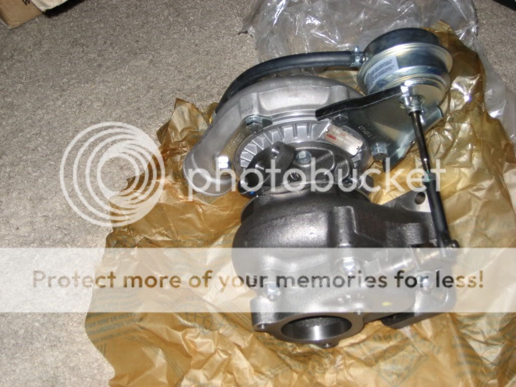
What's the big circular piece that connects to the turbo manifold? - http://i411.photobucket.com/albums/pp195/r.../100_6637-1.jpg
- why does the pipe have that angle coming out of ^that^ piece? Doesn't look efficient. Explain?
What's the bell looking piece at the top? What's the line for? - http://s411.photobucket.com/albums/pp195/r...rent=turbo1.jpg
is the filter really located that closely to the turbo? doesn't that put it directly behind the radiator fan? Any positive or negative effects of this?
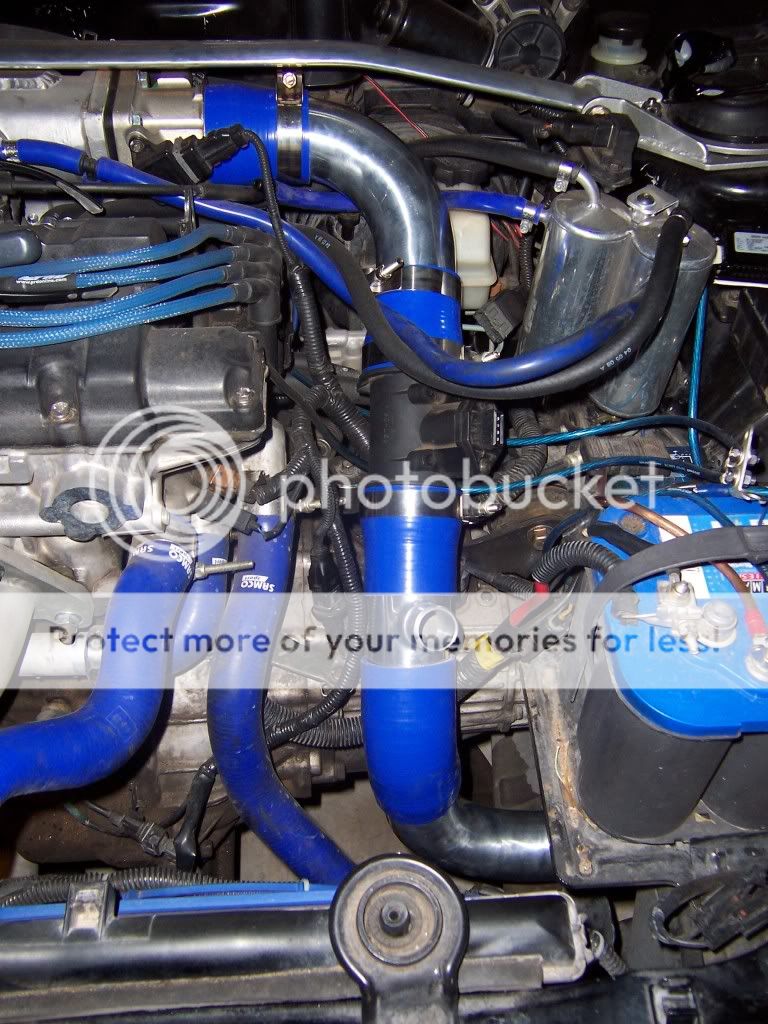
is this the blow off valve? is it placed right before the MAF? http://i411.photobucket.com/albums/pp195/r...aw/100_6615.jpg
[/turbo noob time!!]
http://www.rdtiburon.com/index.php?showtop...&pid=385678
[turbo noob time!!]
What are the nipples at the bottom of the intercooler for?
What's the big circular piece that connects to the turbo manifold? - http://i411.photobucket.com/albums/pp195/r.../100_6637-1.jpg
- why does the pipe have that angle coming out of ^that^ piece? Doesn't look efficient. Explain?
What's the bell looking piece at the top? What's the line for? - http://s411.photobucket.com/albums/pp195/r...rent=turbo1.jpg
is the filter really located that closely to the turbo? doesn't that put it directly behind the radiator fan? Any positive or negative effects of this?
is this the blow off valve? is it placed right before the MAF? http://i411.photobucket.com/albums/pp195/r...aw/100_6615.jpg
[/turbo noob time!!]


Senior Member
Joined: Feb 2009
Posts: 1,932
Likes: 0
From: Boston
Vehicle: 2006 Pontiac GTO
I'll try to answer this post hehe
Hmm.. the turbine? The pipe coming out of it is the downpipe, space is tight and it has to fit. Kit won't be using that downpipe, it came with Tim's manifold.
Wastegate actuator. Line is hooked to compressor output (boost line), gives the signal to the actuator. When boost is high enough, the actuator pulls on the lever and opens the internal wastegate, rerouting part of exhaust gases around the turbine (negative-feedback system to limit maximum boost).
Again, fitment.. Not optimal, but not that important either.. Please note that that picture was just a 'mockup', the kit won't even use that manifold and downpipe, and turbo will sit the other way (compressor to the left).
Yes. Anywhere between compressor and MAF should be ok..
QUOTE
What's the big circular piece that connects to the turbo manifold?
Hmm.. the turbine? The pipe coming out of it is the downpipe, space is tight and it has to fit. Kit won't be using that downpipe, it came with Tim's manifold.
QUOTE
What's the bell looking piece at the top? What's the line for?
Wastegate actuator. Line is hooked to compressor output (boost line), gives the signal to the actuator. When boost is high enough, the actuator pulls on the lever and opens the internal wastegate, rerouting part of exhaust gases around the turbine (negative-feedback system to limit maximum boost).
QUOTE
is the filter really located that closely to the turbo? doesn't that put it directly behind the radiator fan? Any positive or negative effects of this?
Again, fitment.. Not optimal, but not that important either.. Please note that that picture was just a 'mockup', the kit won't even use that manifold and downpipe, and turbo will sit the other way (compressor to the left).
QUOTE
is this the blow off valve? is it placed right before the MAF?
Yes. Anywhere between compressor and MAF should be ok..

Senior Member
Joined: Mar 2006
Posts: 7,799
Likes: 0
Vehicle: 2001 Hyundai Tiburon
Im not seeing the big circle thing.
The bell is the wastegate actuator. The vacuum line is so it knows when to open to let exhaust gas bypass the turbo. This is what controls boost level.
The filter is pretty much placed where there is room for it most of the time. There it should see some cooler air at least. A lot of people run with a filter right on the turbo.
That is the blowoff valve, yes. It is placed after the MAF (dont think Ive seen it before) and vents pressure. Without tuning it should be re-routed back into the intake so the MAF doesnt get confused but I believe the SMT6 or FIC, etc. can compensate for atmospheric blow off.
Senior Member
Joined: Feb 2009
Posts: 1,932
Likes: 0
From: Boston
Vehicle: 2006 Pontiac GTO
^ If it is atmospheric, why would you place it after the MAF and not before? If it's before the MAF, more of the air that escapes wasn't 'registered' by the MAF
And if you route it back to the intake to avoid confusing the MAF, you want to still route it after the MAF, so in that case your MAF would be before the compressor.
And if you route it back to the intake to avoid confusing the MAF, you want to still route it after the MAF, so in that case your MAF would be before the compressor.
Senior Member
Joined: Mar 2006
Posts: 7,799
Likes: 0
Vehicle: 2001 Hyundai Tiburon
Exactly. I just cant recall ever seeing a BOV before the MAF. If its rerouted it would be routed between the MAF and compressor. A perfect example is how the DSMs are setup.
Ive driven cars where someone will just throw a BOV on there and not bother re-routing the air. When you shift you can feel it bog down even. I know it can be compensated for though and Im not positive on how our cars react to it. I would imagine similar though.
Ive driven cars where someone will just throw a BOV on there and not bother re-routing the air. When you shift you can feel it bog down even. I know it can be compensated for though and Im not positive on how our cars react to it. I would imagine similar though.
Thread Starter
Administrator
Joined: Oct 2002
Posts: 13,943
Likes: 0
From: ɯooɹpǝq ɹnoʎ
Vehicle: ǝdnoɔ sısǝuǝƃ
MODS - I will move some of these posts to a separate thread as this one dies down, and I'll label it as the 'Turbo Basics for Noobs' thread. I'd like to keep it here in the meantime, unless SOCKS or others would like them separated now.
I'm not sure if it's two pieces, or just one piece that works together. I see a part at the top and another at the bottom. The top spools the air coming in through the filter? The bottom connects between the manifold and downpipe? Does each have a different name?
also, doesn't this show the BOV going before the MAF? If the BOV regulates the air pressures, should the MAF go after the BOV to know the proper air flow going into the engine?
are the holes on top/bottom just mounting points? - http://i411.photobucket.com/albums/pp195/r...aw/100_6507.jpg
This thread makes me want to install a turbo dance.gif sport11.gif
QUOTE (Ericy321 @ Dec 18 2008, 07:29 PM)
Im not seeing the big circle thing.
I'm not sure if it's two pieces, or just one piece that works together. I see a part at the top and another at the bottom. The top spools the air coming in through the filter? The bottom connects between the manifold and downpipe? Does each have a different name?
also, doesn't this show the BOV going before the MAF? If the BOV regulates the air pressures, should the MAF go after the BOV to know the proper air flow going into the engine?
are the holes on top/bottom just mounting points? - http://i411.photobucket.com/albums/pp195/r...aw/100_6507.jpg
This thread makes me want to install a turbo dance.gif sport11.gif
Senior Member
Joined: Feb 2009
Posts: 1,932
Likes: 0
From: Boston
Vehicle: 2006 Pontiac GTO
Top is compressor. Bottom is turbine. Exhaust enters the turbine, spins the turbine wheel on the shaft and exits the turbine via the bottom "hole" on the side of the turbine. The shaft spins on the other side the compressor wheel which draws air from the top hole and spits it out through the outlet (top-left in that pic).
Go read an article explaining basic stuff first, easier than asking and people replying. Check out the wiki page also http://en.wikipedia.org/wiki/Turbocharger there's a really nice pic in the beginning which shows you what's inside.
I already explained why I in my (noobie) opinion the BOV should go before MAF, as it is in that picture.
Not sure about the IC thingies, might be just mounting points.

Senior Member
Joined: Jan 2008
Posts: 741
Likes: 0
Vehicle: 2001 Tiburon
The bottom piece is the turbine. It receives the exhaust gasses, which spin the turbine, and then the gasses exit the hole on the bottom.
The top piece is the compressor. It is driven by the turbine, sucks air in the hole at the top of the pic (hidden by the angle of the pic) compresses it, and shoots it out the hole on the left.
This is the turbo assembly.
I think the maf should go after the bov, however I've gone through alot of turbo threads here and I believe there are a bunch of people who have the maf pre-bov, and some even pre-turbo. I think the best way would be having it after the BOV, however I've never actually done it. Just seems like that is how it should be since that is what the engine is going to see. Hopefully some others chime in on this.
Senior Member
Joined: Mar 2006
Posts: 7,799
Likes: 0
Vehicle: 2001 Hyundai Tiburon
OK. How that is setup that will work just fine venting to atmosphere then. Didnt know it was setup that way. And Radu, nice to see you learning all this stuff more as it gets closer to your kit being done.