
oxygen sensor wire identification


Thread Starter
Senior Member
Joined: Jul 2010
Posts: 730
Likes: 0
From: United States
Vehicle: 2001 Hyundai Tiburon
could someone help me identify signal, ground, and heater wires
rd1 1997 vin F
My ecu side wires are;
yellow/blk
teal/red
white/red
schematics are impossible to find since i lost my chilton
the oxygen sensor wires are purple, white, gray, and black i think..i bought this one
http://cgi.ebay.com/ebaymotors/?cmd=...K%3AMEWAX%3AIT
this is the sensor i've got
rd1 1997 vin F
My ecu side wires are;
yellow/blk
teal/red
white/red
schematics are impossible to find since i lost my chilton
the oxygen sensor wires are purple, white, gray, and black i think..i bought this one
http://cgi.ebay.com/ebaymotors/?cmd=...K%3AMEWAX%3AIT
this is the sensor i've got

Senior Member

Joined: Aug 2009
Posts: 11,992
Likes: 0
From: Washington D.C.
Vehicle: Hyundai Tiburon FX
i made this diagram for my car also a 1997 years ago. i hope it offers some insight it's for the OEM Hyundai sensor for a 1997. aftermarket sensor colors are different but the order is the same so this should work:
look at the bottom diagram depending on which sensor pre or post-cat you're working on:
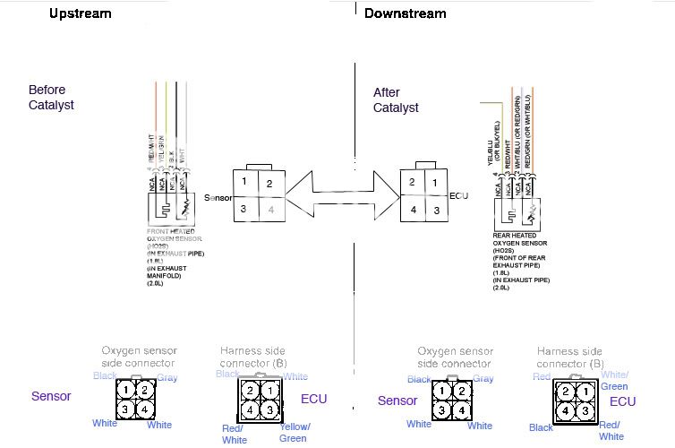
you have to match the ECU colors to the sensor plug order.
the two white wires on the sensor side are heater wires on the OEM sensor, so that tells me the bottom ones are also heaters on your aftermarket sensor in that order therefore the red/white and yellow/green on the bottom are your heaters. then try black to black, and voila 3/4 wires done.
reset the ECU and the codes will go away after an oxygen heater cycle (you have to drive the car around some). if that doesn't work, reverse the two top wires and repeat process. keep doing trial vs. error by switching the horizontal plug order of top and bottom. that gives you 3 or 4 trials of probability to get it right. i did that and it's been working for 4 years so far.
your code depending on which sensor it is should be P0136 for pre-cat, and P0137 post-cat if the wiring order is messed up. there should be no code if wiring is correct.
word of advice: make sure your wires are spliced and connected well. also i highly recommend using the stretchable waterproof electric tape instead of the regular kind once things work. regular electric tape comes undone.
hope that helps some.
look at the bottom diagram depending on which sensor pre or post-cat you're working on:
you have to match the ECU colors to the sensor plug order.
the two white wires on the sensor side are heater wires on the OEM sensor, so that tells me the bottom ones are also heaters on your aftermarket sensor in that order therefore the red/white and yellow/green on the bottom are your heaters. then try black to black, and voila 3/4 wires done.
reset the ECU and the codes will go away after an oxygen heater cycle (you have to drive the car around some). if that doesn't work, reverse the two top wires and repeat process. keep doing trial vs. error by switching the horizontal plug order of top and bottom. that gives you 3 or 4 trials of probability to get it right. i did that and it's been working for 4 years so far.
your code depending on which sensor it is should be P0136 for pre-cat, and P0137 post-cat if the wiring order is messed up. there should be no code if wiring is correct.
word of advice: make sure your wires are spliced and connected well. also i highly recommend using the stretchable waterproof electric tape instead of the regular kind once things work. regular electric tape comes undone.
hope that helps some.
Thread Starter
Senior Member
Joined: Jul 2010
Posts: 730
Likes: 0
From: United States
Vehicle: 2001 Hyundai Tiburon
I NEED AFTER CATALYST, though i wired up the front heated too which worked cause the wires match correctly, but my aftermarket downstream oxygsen sensor seems a bit unique, with that being said; CEL still shows..
the rear heated oxygen sensor (AFTER CATALYST) (front or rear exhaust pipe 1.8 or 2.0 picture with NCA)) 4 NCA))3 NCA))2 NCAA))1 photo at the top dosetn look accurate to the ecu and sensor harness comparison.. were your wires really the same for the downstream oxygen sensor?
the harness connector b in ur schematic says green/yel, white/red again
my wires, in the b harness, for instance; would be vry different from that.
something like
ECU side, they're yel/blk, blu/white, red/white, green/yel [ inverted, opposite of front so its yellow with green centerline line]
this has to be clipped to my oxygen sensor
is that a typo or just accurate? in ur downstream b side compaison that is... just saying
Senior Member
Joined: Aug 2009
Posts: 11,992
Likes: 0
From: Washington D.C.
Vehicle: Hyundai Tiburon FX
the bottom of the diagram is correct with what the colors for mine were. but i have the old plugs like the old Hyundai's used before the wiring order and plugs got switched.
is your plug small square or the bigger one with rounded edges? b/c there are two types of plugs. the newer plugs (bigger with rounded edges) are inverted in which case all of the numbers are reversed. for example 2,1,4,3 on the ECU side becomes 1,2,3,4.
not all of the colors are matched for everyone. it's kind of strange but the way i did it was to try to mostly match the colors to the diagram (centered right on the image).
i tried to match them for you bu it looks like you have multiple colors repeated. haha. that's going to give you a bit of trouble...
is your plug small square or the bigger one with rounded edges? b/c there are two types of plugs. the newer plugs (bigger with rounded edges) are inverted in which case all of the numbers are reversed. for example 2,1,4,3 on the ECU side becomes 1,2,3,4.
ECU side, they're yel/blk, blu/white, red/white, green/yel
not all of the colors are matched for everyone. it's kind of strange but the way i did it was to try to mostly match the colors to the diagram (centered right on the image).
i tried to match them for you bu it looks like you have multiple colors repeated. haha. that's going to give you a bit of trouble...
Thread Starter
Senior Member
Joined: Jul 2010
Posts: 730
Likes: 0
From: United States
Vehicle: 2001 Hyundai Tiburon
Is this diagram still accurate? If it is, it seems that your diagram does not match, since it says that yellow wires are for heaters on yours, hyundaikitcoupe--

Since I spliced my wires, my oxygen sensor wires look like this; obviously green/yellow, red/white, white, white.[/img]
Just trying to make definite sure that my wires are put together right--
green yel > white
red white > white
my oxygen sensor wires are standard black, white x 2, gray
and thats all i got--
since my downstream oxygen sensor is a whole other obstacle
Senior Member
Joined: Aug 2009
Posts: 11,992
Likes: 0
From: Washington D.C.
Vehicle: Hyundai Tiburon FX
i did the same thing by mistake before i knew anything about cars. what you need to do is make sure the aftermarket O2 sensor is fully intact with its plug like it was packaged. then take your old plug that you cut off and clip it into that with the wires hanging out back. then match it via the numbers on the diagram. if you don't have both plugs (Sensor plug to ECU plug) connected somewhere along the connection, then there's no way you can ever be certain you did it correctly.
if you threw your old ECU side plug away like i stupidly did, then you're either going to have to find the same one off a junk car, or find a newer one and mirror the numbers--this is what i did, which confirmed this:
Ultratibby's diagram is for the new sensors, usually for late model 1998-2001 Tiburons. there are two kinds of plugs. one is the old one using my diagram, the other is the new one using Ultratibby (he had a 2001 Tib) in which the order of the numbers has been mirrored (for reasons I don't understand).
^your wires in that photo look like the before-catalyst sensor from the engine bay. that should be cake, and looks like it matches correctly in the exact order of my diagram. i understood that you're having problems with the post-catalyst sensor correct? if so, get me a photo of those wires and make sure you still have all of the plugs because without them you will get nowhere.