
Memoirs Of A Boosthead


Thread Starter
Senior Member
Joined: May 2007
Posts: 869
Likes: 0
Vehicle: 1998 Tiburon
The design is finished and has been approved by the two people who have seen it (who were actually very impressed...) being Thomas and Arthur.
So bored as shit (still disabled) I decided as I couldnt make it to Tom's place right now 'cos Im spastic I decided that I would at least do 'something' to pass the time.
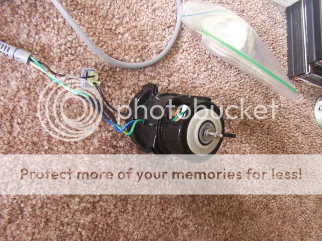
Now this f***er is going to run from this (off an inverter) which is out of a spot scrubber (dust buster thinger) 18,000 RPM, yeah baby !
Now, after seeing that thing crank Tom and Art seemed very impressed. Even more so when I showed them my design and how it would all work. (and they agreed that indeed it would work, though like me had no idea how the results would pan out.. But that's all a part of the fun ;D )
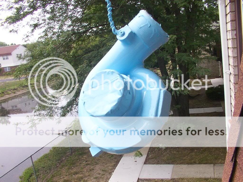
So I decided today that it was time to clean up my charger (super, turbo? you decide !.. Bascally my booster) and paint it.
So the first step was prep work. First I fired up my pretend dremel and grinded off the horrid serial numbers and also a couple of dings in the body.
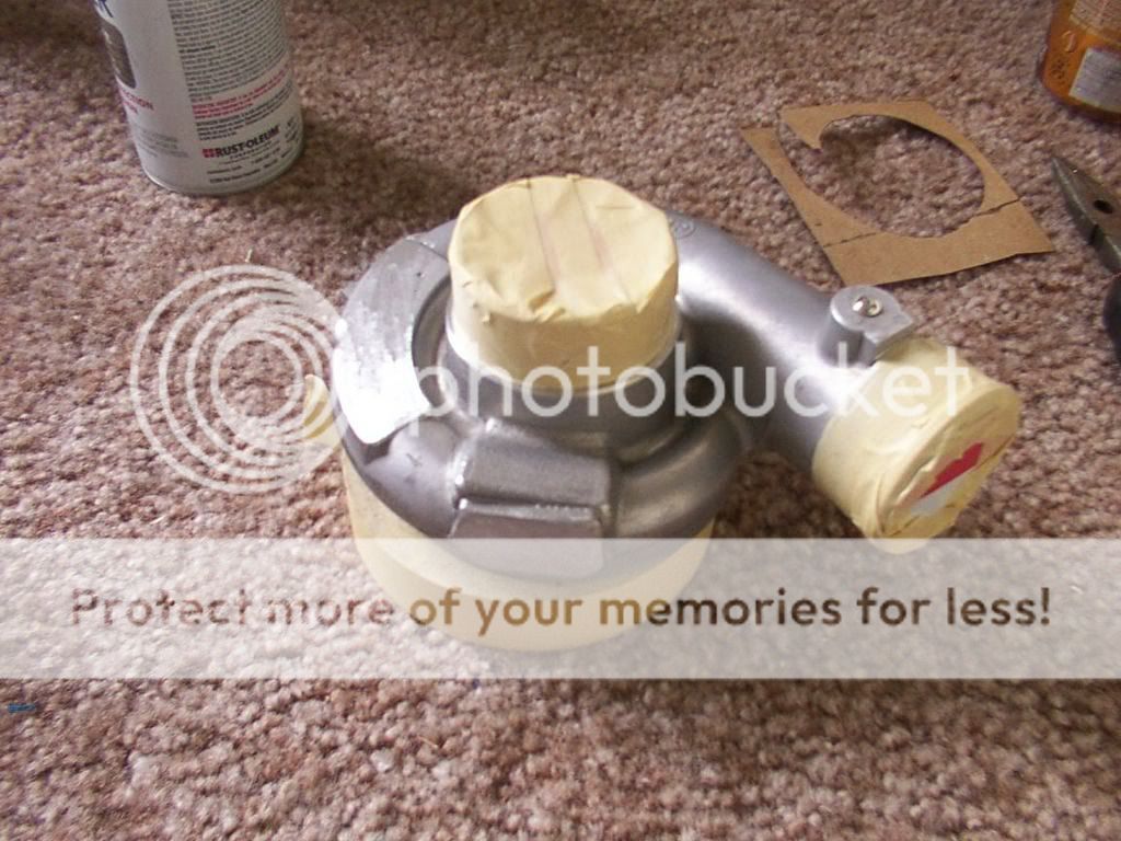
Then I masked the front and back ends of the charger and cleaned them with degreaser. Obviously I wasnt as worried about the bottom half as it's gonna be covered anyways, but I did want it 'clean'
Charger top -
Bottom unit top -

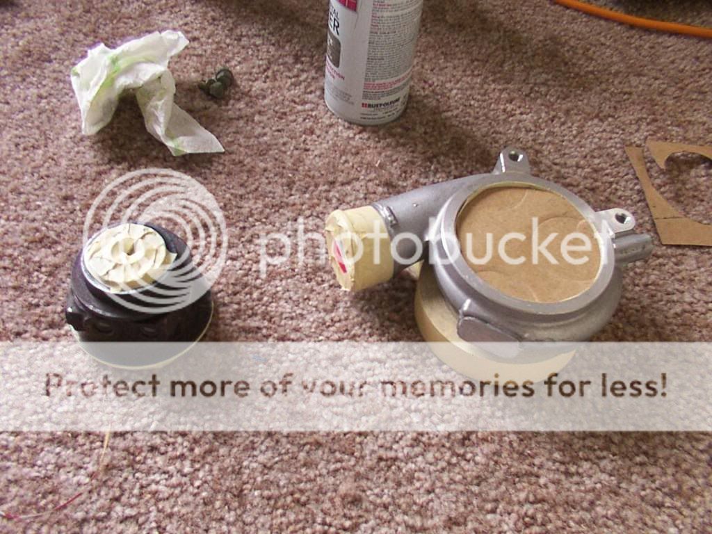
Both from bottom. Now remember kids, prep is 90% of the jobby !
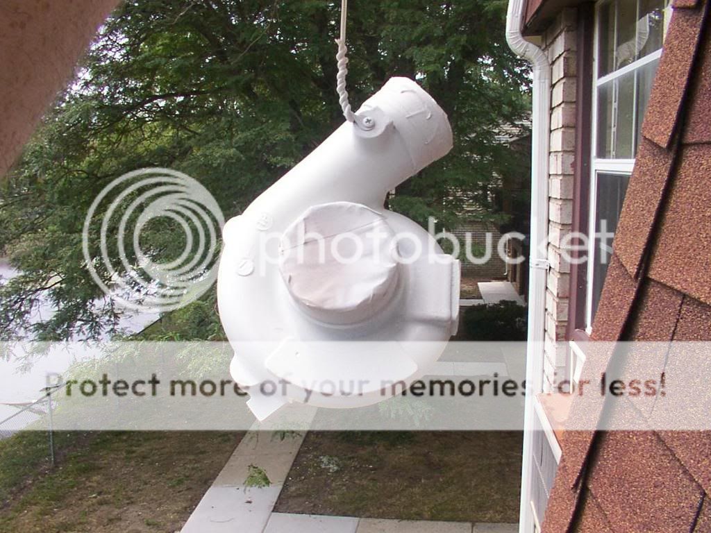
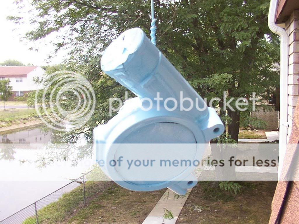
Now anybody who has painted knows that the best way to paint a 3d item (IE - not flat) is to hang it. So here you can see the hung charger pre paint.

And all you need to do is grab the wire high up and twist, and you can get around it easy smile.gif

Time to ready for flight in my star wars space ship... Opps, wrong day ;D OK so it was really time to mask up and put on goggles so I didnt end up with paint all over the lenses of my glasses, or for those who have good eyes not end up with paint on your eyeballs (trust me kids, it's not a nice experience...) Be safe, look like a twat !

Round one, prime time !

Round two, base color. For this I chose baby blue. I have had this f***ing can of Rusto kicking around for five years, I bought them to paint a BMX and had one spare. Finally I decided to use it here just to get rid of it ;D

So basecoat down -


And then to primer the bottom, ooer -

Then clear the body -


And finish painting the bottom smile.gif -

And here is what will keep an eye on my battery whilst I am boosting.

So bored as shit (still disabled) I decided as I couldnt make it to Tom's place right now 'cos Im spastic I decided that I would at least do 'something' to pass the time.
Now this f***er is going to run from this (off an inverter) which is out of a spot scrubber (dust buster thinger) 18,000 RPM, yeah baby !
Now, after seeing that thing crank Tom and Art seemed very impressed. Even more so when I showed them my design and how it would all work. (and they agreed that indeed it would work, though like me had no idea how the results would pan out.. But that's all a part of the fun ;D )
So I decided today that it was time to clean up my charger (super, turbo? you decide !.. Bascally my booster) and paint it.
So the first step was prep work. First I fired up my pretend dremel and grinded off the horrid serial numbers and also a couple of dings in the body.
Then I masked the front and back ends of the charger and cleaned them with degreaser. Obviously I wasnt as worried about the bottom half as it's gonna be covered anyways, but I did want it 'clean'
Charger top -
Bottom unit top -
Both from bottom. Now remember kids, prep is 90% of the jobby !
Now anybody who has painted knows that the best way to paint a 3d item (IE - not flat) is to hang it. So here you can see the hung charger pre paint.
And all you need to do is grab the wire high up and twist, and you can get around it easy smile.gif
Time to ready for flight in my star wars space ship... Opps, wrong day ;D OK so it was really time to mask up and put on goggles so I didnt end up with paint all over the lenses of my glasses, or for those who have good eyes not end up with paint on your eyeballs (trust me kids, it's not a nice experience...) Be safe, look like a twat !
Round one, prime time !
Round two, base color. For this I chose baby blue. I have had this f***ing can of Rusto kicking around for five years, I bought them to paint a BMX and had one spare. Finally I decided to use it here just to get rid of it ;D
So basecoat down -
And then to primer the bottom, ooer -
Then clear the body -
And finish painting the bottom smile.gif -
And here is what will keep an eye on my battery whilst I am boosting.

Thread Starter
Senior Member
Joined: May 2007
Posts: 869
Likes: 0
Vehicle: 1998 Tiburon
It's not a turbo. Well it was, now it's been machined into a electric supercharger.
The motor at the top is 110v and spins 18,000 RPM in about .5 seconds. That will be running into a pulley and there will be a pulley on the spline of the charger.
The ratio over the pulleys and belt is 3:1, giving me a total spin speed of the impellor of 54,000 RPM. Apparently around 44,000 RPM will give me 4-6lbs of boost.
The ex turbo unit itself has been totally stripped and top and bottom ceramic skate bearings are being used. I have also machined a new spline/shaft that holds the impellor and rides in the bearings.
Heat isnt a problem for 2 reasons...
#1 - The unit will only operate for around 4 seconds at a time.
#2 it's electric, so there are no hot gases and it isnt like a belt driven supercharger that spins all the time at various speeds.
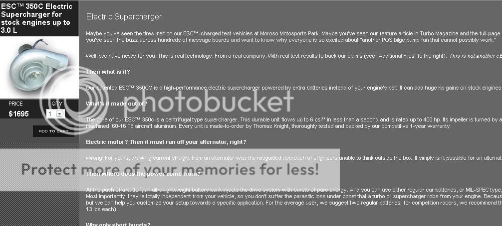
The unit is based from Thomas Knight's original Electric Charger, this uses a heavily modified motor capable of over 50k RPM. The problem is it's nothing more than what I am building here and cost? I'll let you see that.
My turbo was free, the motor came out of a unit I got for $20 @ home depot. Ceramic bearings are around $30 a pair and the shaft and all the other items were $3 from the local steel yard (the new shaft is nothing but a bolt, cost 20 cents and its toughened steel). Belt and pulleys are $23 shipped. So Ill order spares smile.gif
I'll post more on the design of it later, but it WILL work. Everyone who has seen it agrees that it will put out boost. How much? well we wont know that until it's assmebled and benched, but we will get some boost out for less than $200.
Look at what one will cost you and how it's bascically just a turbo with an electric motor on the back. And this one is 36v so you need 3 slave batteries. Im using a 2000w inverter on a 110 motor smile.gif
<div class='quotetop'>QUOTE (majikTib @ Jul 16 2007, 12:13 PM) <{POST_SNAPBACK}></div><div class='quotemain'>but why paint it?</div>
I'm really bored haha.gif
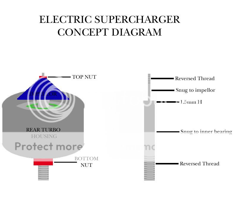
O.K here is how the design works.
Firstly the top of the unit. How to get a bearing in there?
Well there was a part that seals in the shaft. I ground the original top down flat, flipped it and hammered in a washer. It needs a spot weld or 2 to keep it locked there.
Then that will be machined out so the top bearing presses in. Then it goes back into the bottom of the turbo unit with the clip pictured. It also has an inbuilt rubber gasket to seal up the top.

So the bearing at the top will sit in there.
Next up, the second inline bearing. That goes here. This is the bottom end of that back unit. About 3/4 inside the width of the hole gets smaller. So what I am going to do is get the opening machined to again let a bearing be pressed in, it will stop when it gets to the smaller opening, keeping it nice and tight smile.gif

Here is the 'kit' of parts that I am using. Some I made/bought some were off the turbo. So here you can see 2 skate bearings (surrogates to be replaced with ceramics) the shaft (a bolt with the head machined off and the thread left on the bottom) and the impellor with a bolt through it and a brass bearing knuckle.

Now. In the top of the shaft (the non threaded end) I am getting it machined with a thread that the impellor will bolt into, making it one shaft. It will then go together like this .

All the bolts are locking bolts.
And when assembled the bottom of the charger unit will look like this -
And once that is assemlbed the top body of the charger goes back in with a large C clip (again it has a inbuilt rubber gasket to seal).
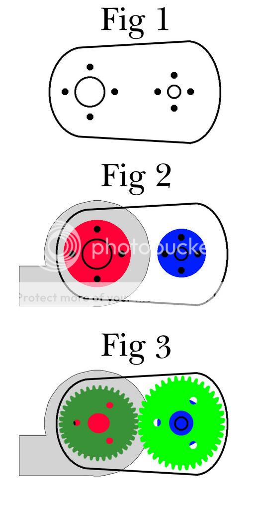
The bottom of the shaft will have a pulley wheel on it (the 1 part of the 3:1 ratio) and the motor will host the bigger pulley wheel (the 3 part of the 3:1 ratio). At which point an aluminum plate (8mm) will be cut in an oval and bolt into the bottom of the turbo and the motor.
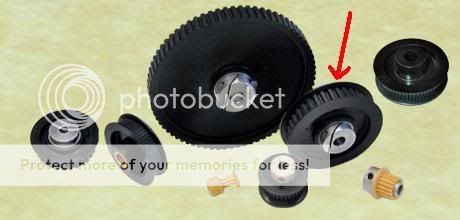
Pulley wheels, these use a belt thats akin to an alternator belt
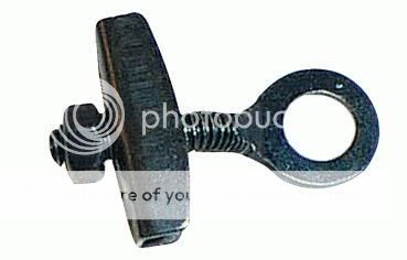
There are 4 bolts that will hold the charger onto the alu plate. 2 of them will use these ICTs on the edge of the plate pulling the belt tight.
And the completed unit will look something like this. But of course, there will be a steel casing made from thin steel that will cover the whole belt system incase of belt failure smile.gif
And then I am running a 2000w inverter which will be piggybacked with a 1 farad cap to provide juice. Then it will be wired into the battery and will operate in 4-5 second 'spurts' providing raw boost into the CAI. If the unit provides more than 6lbs of boost I am going to use a dump valve that releases pressure at 6. I dont want to boost anymore than 6lbs on stock internals and an auto trans because I fear something will go horribly bad if I do haha.gif
Edit. Please note I am no longer using gears as these would need to be encased and run with fluid. I changed the design to use belts and pulleys instead smile.gif
The motor at the top is 110v and spins 18,000 RPM in about .5 seconds. That will be running into a pulley and there will be a pulley on the spline of the charger.
The ratio over the pulleys and belt is 3:1, giving me a total spin speed of the impellor of 54,000 RPM. Apparently around 44,000 RPM will give me 4-6lbs of boost.
The ex turbo unit itself has been totally stripped and top and bottom ceramic skate bearings are being used. I have also machined a new spline/shaft that holds the impellor and rides in the bearings.
Heat isnt a problem for 2 reasons...
#1 - The unit will only operate for around 4 seconds at a time.
#2 it's electric, so there are no hot gases and it isnt like a belt driven supercharger that spins all the time at various speeds.
The unit is based from Thomas Knight's original Electric Charger, this uses a heavily modified motor capable of over 50k RPM. The problem is it's nothing more than what I am building here and cost? I'll let you see that.
My turbo was free, the motor came out of a unit I got for $20 @ home depot. Ceramic bearings are around $30 a pair and the shaft and all the other items were $3 from the local steel yard (the new shaft is nothing but a bolt, cost 20 cents and its toughened steel). Belt and pulleys are $23 shipped. So Ill order spares smile.gif
I'll post more on the design of it later, but it WILL work. Everyone who has seen it agrees that it will put out boost. How much? well we wont know that until it's assmebled and benched, but we will get some boost out for less than $200.
Look at what one will cost you and how it's bascically just a turbo with an electric motor on the back. And this one is 36v so you need 3 slave batteries. Im using a 2000w inverter on a 110 motor smile.gif
<div class='quotetop'>QUOTE (majikTib @ Jul 16 2007, 12:13 PM) <{POST_SNAPBACK}></div><div class='quotemain'>but why paint it?</div>
I'm really bored haha.gif
O.K here is how the design works.
Firstly the top of the unit. How to get a bearing in there?
Well there was a part that seals in the shaft. I ground the original top down flat, flipped it and hammered in a washer. It needs a spot weld or 2 to keep it locked there.
Then that will be machined out so the top bearing presses in. Then it goes back into the bottom of the turbo unit with the clip pictured. It also has an inbuilt rubber gasket to seal up the top.
So the bearing at the top will sit in there.
Next up, the second inline bearing. That goes here. This is the bottom end of that back unit. About 3/4 inside the width of the hole gets smaller. So what I am going to do is get the opening machined to again let a bearing be pressed in, it will stop when it gets to the smaller opening, keeping it nice and tight smile.gif
Here is the 'kit' of parts that I am using. Some I made/bought some were off the turbo. So here you can see 2 skate bearings (surrogates to be replaced with ceramics) the shaft (a bolt with the head machined off and the thread left on the bottom) and the impellor with a bolt through it and a brass bearing knuckle.
Now. In the top of the shaft (the non threaded end) I am getting it machined with a thread that the impellor will bolt into, making it one shaft. It will then go together like this .
All the bolts are locking bolts.
And when assembled the bottom of the charger unit will look like this -
And once that is assemlbed the top body of the charger goes back in with a large C clip (again it has a inbuilt rubber gasket to seal).
The bottom of the shaft will have a pulley wheel on it (the 1 part of the 3:1 ratio) and the motor will host the bigger pulley wheel (the 3 part of the 3:1 ratio). At which point an aluminum plate (8mm) will be cut in an oval and bolt into the bottom of the turbo and the motor.
Pulley wheels, these use a belt thats akin to an alternator belt
There are 4 bolts that will hold the charger onto the alu plate. 2 of them will use these ICTs on the edge of the plate pulling the belt tight.
And the completed unit will look something like this. But of course, there will be a steel casing made from thin steel that will cover the whole belt system incase of belt failure smile.gif
And then I am running a 2000w inverter which will be piggybacked with a 1 farad cap to provide juice. Then it will be wired into the battery and will operate in 4-5 second 'spurts' providing raw boost into the CAI. If the unit provides more than 6lbs of boost I am going to use a dump valve that releases pressure at 6. I dont want to boost anymore than 6lbs on stock internals and an auto trans because I fear something will go horribly bad if I do haha.gif
Edit. Please note I am no longer using gears as these would need to be encased and run with fluid. I changed the design to use belts and pulleys instead smile.gif
Senior Member

Joined: Nov 2008
Posts: 2,881
Likes: 0
From: Huntsville, AL
Vehicle: 2001/Hyundai/Tiburon
Looking great Pandy, you going to start selling a few of them once you get it working?!!
I'm still confused about the pulleys, what are they for? Also, how are you going to regulate it with your RPMs? I'm guessing those two questions answer each other, but I'm lost at the moment...
Also, where will the charger be located, and where are you going to have all those extra batteries?
Lots of questions, but you really piqued my interest here...

Moderator

Joined: Feb 2009
Posts: 11,732
Likes: 5
From: Leesville, Louisiana
Vehicle: 2001 Hyundai Tiburon
How many amps is that motor? It dosnt' look like it has the beef required. When you said a motor, I was thinking these 8 amp 20,000RPM motors. I'm now wondering if it can boost much at all with that setup.
Thread Starter
Senior Member
Joined: May 2007
Posts: 869
Likes: 0
Vehicle: 1998 Tiburon
DTN. No idea. But it has a shitload of torque, you cannot stop it by hand. Anyways this will be a very easy spinning setup, the bearings (ceramic) create practically zero lag..
If the motor was powerful enough to suck water all the way through a vacuum cleaner it should have enough power to spin a small steel shaft with an impellor on the end..
SE - no I wont be selling them as alot of the parts I have here I got free by donation. Plus the time it takes would seriously rack up the $$. I mean if I had to buy the turbo we would be talking serious money before I even started, then there is all the machine work needed and so on..
The pulleys are going to create a 3:1 ratio. So the drive pulley on the motor will be 3 times bigger than the pulley on the shaft with the impellor on. This will multiply the spin output of the motor from 18,000 RPM to the needed 50k+ RPM to create enough boost. Your average turbocharger spins at around 44,000 RPM to generate 3-4 lbs of boost. So to get anything significant you need it spinning there or faster..
The charger 'lump' will be located somewhere in the engine bay battery side. The input pipe will channel right into the front bumper and will have a cone filter on, and the output will plumb into the CAI. I will remove the first main elbow of the CAI and channel the output air from the charger into the CAI. The air sensor below the MAF will be put into the boost pipe outlet of the charger..
The boost output can be controlled by getting a specific blow off valve that will release any pressure above what it is tuned to, so that isnt a concern..
OK, now the battery 'problem'. Thats really simple. Thomas Knight uses a 12v motor, basically. I would imagine it is a rewound heater blower motor from a car (possibly something big like a suburban or similar) he then uses a 3 battery setup to overpower the motor with 36v, creating the kind of RPM output that you need to get boost.
Instead of that I have designed a hybrid of his 2 available systems. One uses a 12v motor @ 36v off 3 slave batteries. They need charging all the time, so thats a no no, I also dont have a trunk so have nowhere to fit them.
The other type of charger he does goes on your engine belts and piggy baks off your alternator. So I took both ideas and am using a 110v motor on a 2000w power inverter, this will run from my existing 12v car power BUT I will be using a car stereo capacitor to store power for boost (instead of an amplifier) The cap will be wired from my car battery, then that will run into the inverter. Boost times per boost will be around 4-6 seconds (long enough to get me over 70mph in the midpoint of acceleration) and will then stop boosting. So I dont need constant power to the charger, only when it will be in use.
I am pretty positive that this way of powering it will work, because I have three car amps in my car (two of which run @ 16 volts) and they sit on a 5 farad capacitor. I get no dimming of my electrical system AT ALL and no drain on my alternator causing me loss of WHP.
So Im pretty sure it will all work out fine smile.gif
One other thing for DTN..
The motor from the vacuum had a impellor bolted to it that I removed. It was bigger than the plastic flywheel I will be using and no doubt heavier too, plus it was sucking air so there was drag and the vacuum was still really powerful.
Ooo just thought of something. Did anyone ever see that episode of Mythbusters where Adam made a hovercraft using ONE vacuum cleaner motor? well it worked, and was enough to lift a 6ft circle of 3/4 ply along with a desk chair with Adam sitting on it.. It also had enough suction power to suck in his lip from over an inch away LMAO. So Im pretty sure it has the power needed smile.gif
Moderator
Joined: Feb 2009
Posts: 11,732
Likes: 5
From: Leesville, Louisiana
Vehicle: 2001 Hyundai Tiburon
Dang man, that's one heck of a power inverter... If it all fails let me know. I'm guessing that is a 4A motor you have there. Your power supply can handle up to 18A. So if it dosn't work on the first attempt, you can always double up the motors for almost twice the power. If it all falls through, I may be able to get ahold of a 9A motor.
I really hope this works, but remember you're decreasing the torque 4X to increase the speed 4X
I really hope this works, but remember you're decreasing the torque 4X to increase the speed 4X
Senior Member
Joined: Nov 2008
Posts: 2,881
Likes: 0
From: Huntsville, AL
Vehicle: 2001/Hyundai/Tiburon
Ah, so much clearer now, thanks! So you're only going to have boost for a few seconds when you want it? Besides a huge power drain, what's preventing you from running it full time? And how are you going to control when it's on and how much power it will take (or will it be running full power all the time?) Then when it's not running, how well will air flow through there? Seems like you'd have a big non-working turbo in the way of your airflow in to your intake...
You better be keeping a good set of pics of everything so you can do a great writeup/DIY when you're finished!
You better be keeping a good set of pics of everything so you can do a great writeup/DIY when you're finished!
Moderator
Joined: Feb 2009
Posts: 11,732
Likes: 5
From: Leesville, Louisiana
Vehicle: 2001 Hyundai Tiburon
^^ I was thinking the same thing, which is why I suggested using a 3" check valve in paralell with it in the origonal post. But it may be that the blades won't interfere with the flow.