
Diy Turbo Manifold


Thread Starter
Senior Member

Joined: Sep 2009
Posts: 4,185
Likes: 0
Vehicle: Elantra HD / 2007
This article was written by TCR AUTOMOTIVE AND PERFORMANCE
http://toyotaperformance.com/turbo_header.htm
This article details the process of fabricating a low cost turbo header. The subject engine is a Toyota 22RE engine using a Garrett T4/T3 hybrid turbo.
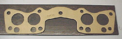
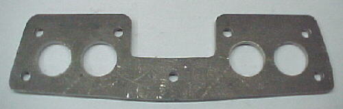
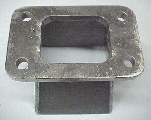
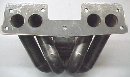
<span style="font-size:14pt;line-height:100%">Flanges</span>
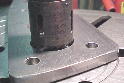
The head and turbo flanges are laid out on 3/8 to 1/2 inch mild steel plates using the gaskets as tracing patterns. A drill press and hole saw are used to cut the holes. For rectangular holes, 4 smaller holes may have to be drilled and then hand filed to obtain the correct shape. If you have access to a plasma arc cutter, this job will go much faster!
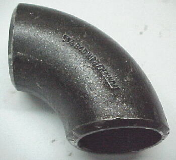
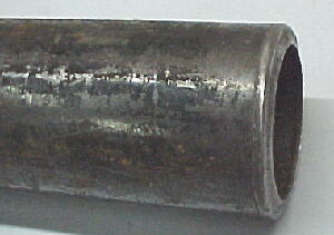
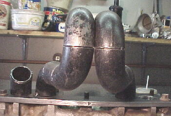
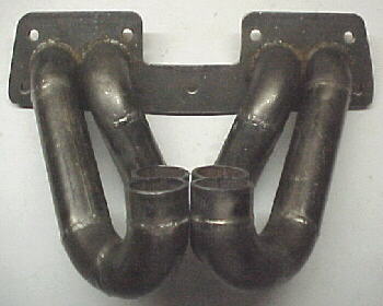
<span style="font-size:14pt;line-height:100%">Tubes</span>
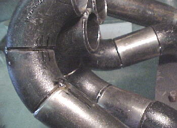
This header was constructed from 1 1/4 schedule 40 NSP weld els and tubing. The els are available from most industrial plumbing and gas fitting shops and are very inexpensive. They are made from a high strength, weldable alloy steel and have a nice V at each end to pour in a good, strong weld. They are available in 45 and 90 degree bends and short and standard radius styles. We recommend using the standard, longer radius ones whenever possible as they have less flow restriction. The els are also available in different IDs. The size describes the approximate ID, not the OD. The 1 1/4 ones are actually about 1 3/8 ID. Straight schedule 40 NSP tubing is used between els. These parts have a very thick wall thickness so the header will probably weigh as much as a heavy cast iron manifold. This thickness is necessary with non-stainless tubing for longevity at the high temperatures encountered. Standard mild steel header tubing will quickly self destruct if used for a turbo header. These materials have proved to last for several years of hard use on many engines including road racing applications.
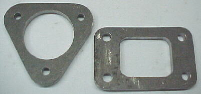
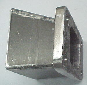
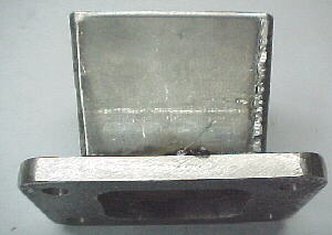
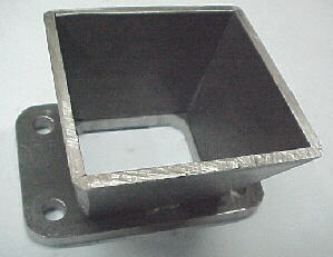
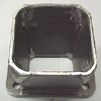
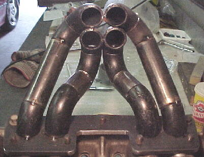
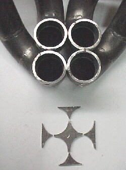
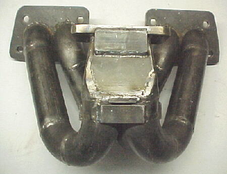
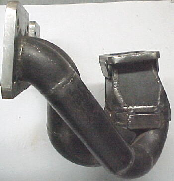
<span style="font-size:14pt;line-height:100%">Collector</span>
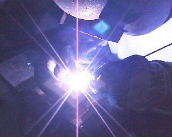
The collector is what merges the primary tubes into the turbine inlet. It needs to match the outer circumference of the primary tubes and the ID at the turbine flange needs to match the hole ID. It is constructed in 4 main parts, made from 1/8 to 3/16 plate stock which is then welded together. Later, 4 wedges wre cut from each corner and 45 degree triangles were added to help match the tube contours. Alternately, an 8 sided collector can be built or a hammer formed collector made. Hammer forming such thick plate is very time consuming! For Turbos with round inlet holes, a conical collector needs to be made. This entails cutting a paper template to simulate the size and shape and lots of cursing and swearing to heat and hammer form into the conical shape. We recommend that all parts be TIG welded to reduce warpage. Weld the turbine inlet flange to the collector.
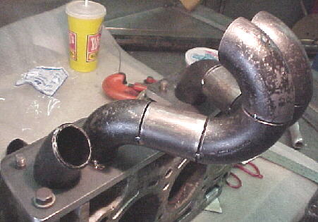
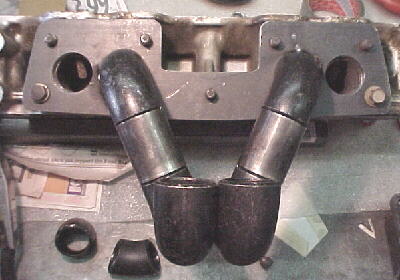
<span style="font-size:14pt;line-height:100%">Tube Layout</span>
The turbo should be held in position where it will be mounted. Lots of thought should go into the tube layout to try to maintain equal lengths if possible and be sure that the tubes clear steering boxes, master cylinders, strut towers etc. It has been found that actual tube length seems to have little effect on response or power in street applications however, equal lengths will theoretically give slightly better response. Most of our systems have a 14 to 18 inch primary tube length and this has worked well.
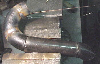
The 45 and 90 degree els and straight tubing may be duct taped together to plan the layout. Once you are satisfied with the layout, the tubes may be tacked to the head flange with ONE small tack on the top. We bolt the flange to a scrap head to aid in tube alignment. Start out from the head flange one piece at a time working out towards the collector.
Once your pipes are all tacked and line up on the collector ok, carefully bolt the assembly into the car and set the turbo and collector in place. If everything is where you want it, remove and take it back to the bench. Scribe or mark each tube where it meets the flange and number each tube. Tack each joint in at least 2 points EXCEPT at the head flange. Now carefully break each tube off of the flange. Weld all the joints completely on each tube.
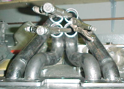
Once all the primary tube joints have been welded, they need to be carefully repositioned as they were before removal from the head flange. Line up your scribe marks and the original tacks. Tack each tube back in place. The tubes may be moved and twisted slightly to allow the collector ends to meet at the proper angle and height to align with the collector base. A large hose clamp or vise grips can be used to hold the tubes together. Once you are satisfied, heavily tack the primaries to the head flange and the ends of the tubes together. Make sure that the flange is firmly bolted to a scrap head or 1 inch base plate to prevent warpage. Yes, even 1/2 inch plate will warp.
<span style="font-size:14pt;line-height:100%">Center Diamond and Corners</span>
You need to cut and shape corner pieces and a center diamond to plug the holes where the collector meets the primaries. These should be cut from the 1/8 or 3/16 plate that you used to make the collector. Once satisfied with the fit, weld in place.
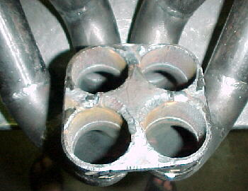
You are now ready to weld the collector to the rest of the header. 1/8 X 1 flat stock can be used to brace the edge of the flange to the collector and to the outside of the primaries for extra strength and longevity.
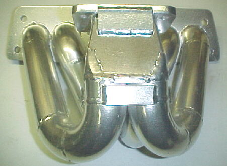
After ceramic coating
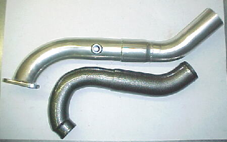
Coated down pipe and powder coated intercooler pipe
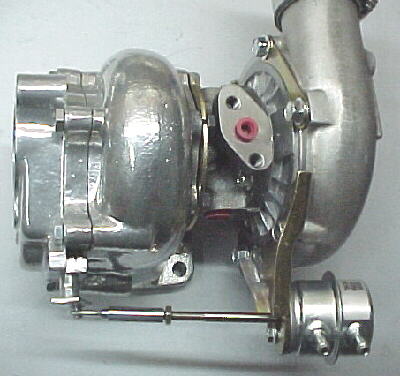
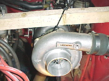
T4/T3 hybrid turbo with H3 compressor, stage 3, .63 exhaust, ceramic coated. A twin port, waste gate actuator is used for cockpit adjustable boost via an inexpensive pneumatic regulator.
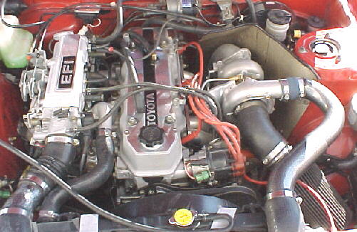
Complete installation. Note extensive heat shield to protect master cylinder and brake lines made from aluminum backed Felramic 2000 material.
http://toyotaperformance.com/turbo_header.htm
This article details the process of fabricating a low cost turbo header. The subject engine is a Toyota 22RE engine using a Garrett T4/T3 hybrid turbo.
<span style="font-size:14pt;line-height:100%">Flanges</span>
The head and turbo flanges are laid out on 3/8 to 1/2 inch mild steel plates using the gaskets as tracing patterns. A drill press and hole saw are used to cut the holes. For rectangular holes, 4 smaller holes may have to be drilled and then hand filed to obtain the correct shape. If you have access to a plasma arc cutter, this job will go much faster!
<span style="font-size:14pt;line-height:100%">Tubes</span>
This header was constructed from 1 1/4 schedule 40 NSP weld els and tubing. The els are available from most industrial plumbing and gas fitting shops and are very inexpensive. They are made from a high strength, weldable alloy steel and have a nice V at each end to pour in a good, strong weld. They are available in 45 and 90 degree bends and short and standard radius styles. We recommend using the standard, longer radius ones whenever possible as they have less flow restriction. The els are also available in different IDs. The size describes the approximate ID, not the OD. The 1 1/4 ones are actually about 1 3/8 ID. Straight schedule 40 NSP tubing is used between els. These parts have a very thick wall thickness so the header will probably weigh as much as a heavy cast iron manifold. This thickness is necessary with non-stainless tubing for longevity at the high temperatures encountered. Standard mild steel header tubing will quickly self destruct if used for a turbo header. These materials have proved to last for several years of hard use on many engines including road racing applications.
<span style="font-size:14pt;line-height:100%">Collector</span>
The collector is what merges the primary tubes into the turbine inlet. It needs to match the outer circumference of the primary tubes and the ID at the turbine flange needs to match the hole ID. It is constructed in 4 main parts, made from 1/8 to 3/16 plate stock which is then welded together. Later, 4 wedges wre cut from each corner and 45 degree triangles were added to help match the tube contours. Alternately, an 8 sided collector can be built or a hammer formed collector made. Hammer forming such thick plate is very time consuming! For Turbos with round inlet holes, a conical collector needs to be made. This entails cutting a paper template to simulate the size and shape and lots of cursing and swearing to heat and hammer form into the conical shape. We recommend that all parts be TIG welded to reduce warpage. Weld the turbine inlet flange to the collector.
<span style="font-size:14pt;line-height:100%">Tube Layout</span>
The turbo should be held in position where it will be mounted. Lots of thought should go into the tube layout to try to maintain equal lengths if possible and be sure that the tubes clear steering boxes, master cylinders, strut towers etc. It has been found that actual tube length seems to have little effect on response or power in street applications however, equal lengths will theoretically give slightly better response. Most of our systems have a 14 to 18 inch primary tube length and this has worked well.
The 45 and 90 degree els and straight tubing may be duct taped together to plan the layout. Once you are satisfied with the layout, the tubes may be tacked to the head flange with ONE small tack on the top. We bolt the flange to a scrap head to aid in tube alignment. Start out from the head flange one piece at a time working out towards the collector.
Once your pipes are all tacked and line up on the collector ok, carefully bolt the assembly into the car and set the turbo and collector in place. If everything is where you want it, remove and take it back to the bench. Scribe or mark each tube where it meets the flange and number each tube. Tack each joint in at least 2 points EXCEPT at the head flange. Now carefully break each tube off of the flange. Weld all the joints completely on each tube.
Once all the primary tube joints have been welded, they need to be carefully repositioned as they were before removal from the head flange. Line up your scribe marks and the original tacks. Tack each tube back in place. The tubes may be moved and twisted slightly to allow the collector ends to meet at the proper angle and height to align with the collector base. A large hose clamp or vise grips can be used to hold the tubes together. Once you are satisfied, heavily tack the primaries to the head flange and the ends of the tubes together. Make sure that the flange is firmly bolted to a scrap head or 1 inch base plate to prevent warpage. Yes, even 1/2 inch plate will warp.
<span style="font-size:14pt;line-height:100%">Center Diamond and Corners</span>
You need to cut and shape corner pieces and a center diamond to plug the holes where the collector meets the primaries. These should be cut from the 1/8 or 3/16 plate that you used to make the collector. Once satisfied with the fit, weld in place.
You are now ready to weld the collector to the rest of the header. 1/8 X 1 flat stock can be used to brace the edge of the flange to the collector and to the outside of the primaries for extra strength and longevity.
After ceramic coating
Coated down pipe and powder coated intercooler pipe
T4/T3 hybrid turbo with H3 compressor, stage 3, .63 exhaust, ceramic coated. A twin port, waste gate actuator is used for cockpit adjustable boost via an inexpensive pneumatic regulator.
Complete installation. Note extensive heat shield to protect master cylinder and brake lines made from aluminum backed Felramic 2000 material.

Senior Member
Joined: Mar 2006
Posts: 4,244
Likes: 0
From: Ashland, KY
Vehicle: 2001/Hyundai/Tiburon
why's that viper? due to not notching the pipes and making it a cleaner merge?
faith i think its made that way because of space concerns. look at the pic of it in the bay, there's not much other way to put it in there.
hum.. I just looked at that engine bay pic closer... man is that normal? Is it just me or is that huge heat shield kinda of an after thought to fix a bad design issue?

Senior Member
Joined: Mar 2006
Posts: 9,172
Likes: 0
Vehicle: 2001/Hyundai/Tiburon
for the rookie booster and welder it will work fine though. obviously anyone who seeks to achieve high hp numbers and will be making things themselves should already know thats a crappy merge.
ideally, you want the exhaust streams to combine into one stream before entering the turbo. it seems like that merge will restrict by a lot more.
ideally, you want the exhaust streams to combine into one stream before entering the turbo. it seems like that merge will restrict by a lot more.