


Diy Pix For Leds In Heater And Tibby01's Switch Mod


Senior Member
Joined: Feb 2009
Posts: 1,932
Likes: 0
From: Boston
Vehicle: 2006 Pontiac GTO

Sorry to revive this. I have a question about the A/C and recirculate switches. Do you need a resistor to replace the small "blue" bulb? I tried to look at the circuit for the A/C switches, it seems it goes through a diode and a 7.2 Ohm resistor (violet/red/gold).. So I guess i do need a resistor, but in the pictures I see the LED is soldered directly where the bulb was.. Perhaps cut out the 7.2Ohm resistor from the board and put a 510 Ohm one?

Senior Member

Joined: Nov 2008
Posts: 2,881
Likes: 0
From: Huntsville, AL
Vehicle: 2001/Hyundai/Tiburon
The middle blue lamp is a bulb, not an LED, so you do need to put a resistor in it. The blue is just a sleeve over the bulb, the other two green ones are LEDs. The bulb has to have a resistor, the other two already have a resistor in line, so you don't need to.
You can see the resistor in the middle, in this pic:
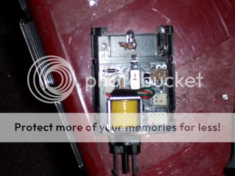
You can see the resistor in the middle, in this pic:

Senior Member
Joined: Feb 2006
Posts: 977
Likes: 0
From: Hereford Az.
^^^ What he said. Oh btw, the center led solder as if it was for an RD1. The poles are the same. I soldered it as is says here on the DIY but it didnt work, then turned it around and soldered it as if it was a RD1 and it worked.
What color of LEDs are you putting in? I ask this becuase i have Red LEDs in mine and they light up good with 470 OHM resistors but i didnt the cruise and rear window defrost switches with 510 OHM resistors and they beraly light up.
What color of LEDs are you putting in? I ask this becuase i have Red LEDs in mine and they light up good with 470 OHM resistors but i didnt the cruise and rear window defrost switches with 510 OHM resistors and they beraly light up.
Senior Member
Joined: Feb 2009
Posts: 1,932
Likes: 0
From: Boston
Vehicle: 2006 Pontiac GTO
Thanks guys, just wanted to make sure. That bulb with the blue sleeve is so small, I thought it might not be 12V..
I'm putting in blue leds, 3mm. They came with resistors, don't remember for sure what value they are but they're ok (I put one in the dimmer switch a while ago and it looks great)
I'm putting in blue leds, 3mm. They came with resistors, don't remember for sure what value they are but they're ok (I put one in the dimmer switch a while ago and it looks great)
Senior Member
Joined: Nov 2008
Posts: 2,881
Likes: 0
From: Huntsville, AL
Vehicle: 2001/Hyundai/Tiburon
Yeah, I wondered that about those little bulbs too... But the LEDs perform fine in them. The resistors that came with your LEDs are probably the 470 ohm ones, I think that's kinda the standard for it.
For the other LEDs in those switches, carefully track which is positive and negative, it can be tricky. Test it if you're able (you can even put a battery to the ones on there to see what's + and -, then use that when installing the new ones).
For the other LEDs in those switches, carefully track which is positive and negative, it can be tricky. Test it if you're able (you can even put a battery to the ones on there to see what's + and -, then use that when installing the new ones).

Thread Starter
Moderator

Joined: Feb 2009
Posts: 11,732
Likes: 5
From: Leesville, Louisiana
Vehicle: 2001 Hyundai Tiburon
I always order the proper resistor from the people who send the LEDs. 470 is too low of ohms for a red LED. Should be a bit higher. You're overdriving the LED at 12V. On a hot day if you drive with your lights on, you may end up loosing a few LEDs.
Senior Member
Joined: Feb 2009
Posts: 1,932
Likes: 0
From: Boston
Vehicle: 2006 Pontiac GTO
I just did the LEDs in heater thing (method 1). It went really well. Here's my 0.02:
- be careful with the clear acrylic, it cracks very easily. It cracked in several places while I worked with it, I used a lot of clear cement.
- I had a couple of 8mm LEDs (huge!), they fit right in the stock bulb holes. File them flat, stick them in, put whiteout right in front of them, and a lot of light will reflect from there. It will help a little at least.
- be careful when working with all these substances, I was careless and got a lot of stuff (solder flux, cement, epoxy) on my hands and probably touched my face afterwards, and I got an irritation right under my eye, it kinda hurts.
Anywhoo, I was very pleasantly surprised when I finished, they look neat (didn't even use any stencil material or anything):
http://picasaweb.google.com/radu.rd2/DashW...652186590142674
Thanks for the DIY, and thanks for gophins349 for the cluster smile.gif
- be careful with the clear acrylic, it cracks very easily. It cracked in several places while I worked with it, I used a lot of clear cement.
- I had a couple of 8mm LEDs (huge!), they fit right in the stock bulb holes. File them flat, stick them in, put whiteout right in front of them, and a lot of light will reflect from there. It will help a little at least.
- be careful when working with all these substances, I was careless and got a lot of stuff (solder flux, cement, epoxy) on my hands and probably touched my face afterwards, and I got an irritation right under my eye, it kinda hurts.
Anywhoo, I was very pleasantly surprised when I finished, they look neat (didn't even use any stencil material or anything):
http://picasaweb.google.com/radu.rd2/DashW...652186590142674
Thanks for the DIY, and thanks for gophins349 for the cluster smile.gif

Senior Member
Joined: Feb 2009
Posts: 1,932
Likes: 0
From: Boston
Vehicle: 2006 Pontiac GTO
I did mine again because some of the LEDs went bad and were blinking (probably because i used some shitty solder which required too much heat). I wanted to do something to it anyway because it was too bright.
I did something similar to method 2, but instead of drilling holes I used hot glue to put the LEDs in the places I wanted. For the knob indicators, I taped LEDs onto their shafts, so that the led shines exactly where it needs to all the time (it rotates with the knob).
I learned that you can grossly overestimate the resistor sizes, I have only like 10mA going through each LED instead of 20mA, and they are still bright and will probably last more this way.
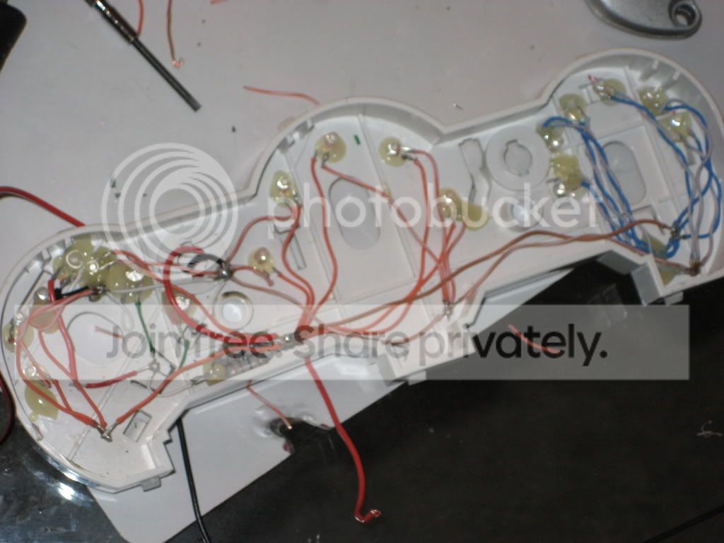
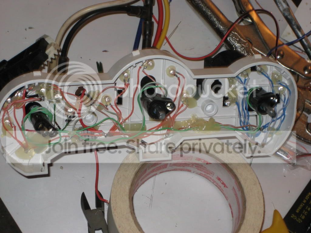
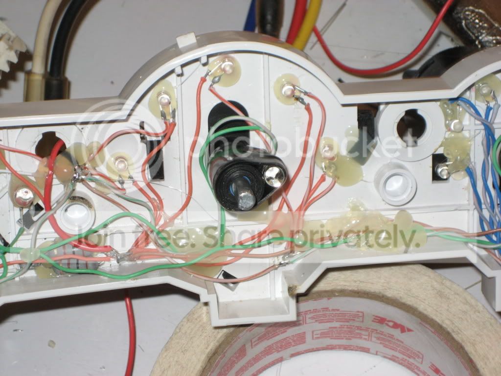
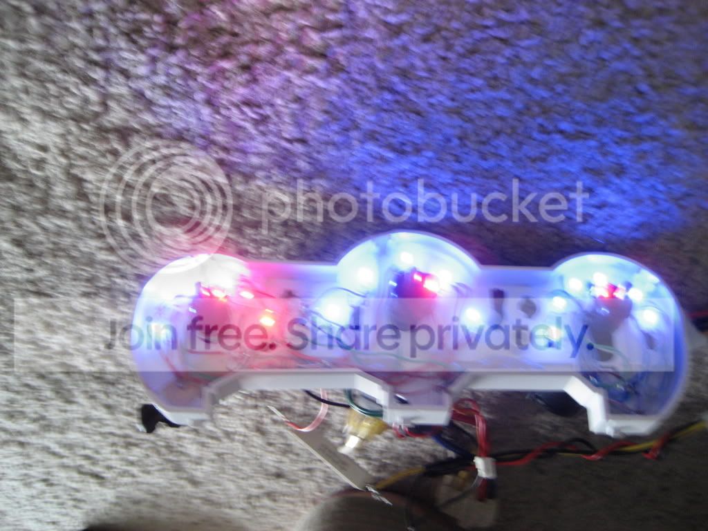

I did something similar to method 2, but instead of drilling holes I used hot glue to put the LEDs in the places I wanted. For the knob indicators, I taped LEDs onto their shafts, so that the led shines exactly where it needs to all the time (it rotates with the knob).
I learned that you can grossly overestimate the resistor sizes, I have only like 10mA going through each LED instead of 20mA, and they are still bright and will probably last more this way.
Thread Starter
Moderator
Joined: Feb 2009
Posts: 11,732
Likes: 5
From: Leesville, Louisiana
Vehicle: 2001 Hyundai Tiburon
Hey, that's pretty hard core man! I'd just be worried about the LEDs on the shaft. I hate adding moving parts to anything. Did you work something out for that?
I just noticed that you used a single resistor bank for all of those LEDs. This can lead to problems later. If an LED goes out by shorting internally, then the resistors can all go out, or cause a fire inside the housing from overheating. Also, a single resistor setup does not provide for any sort of regulation. If a LED forward bias drops, then it will start pulling more power from the rest. If any LEDs go out, then the mass power requirement drops and you start overpowering every LED. It's good that you're running them on 10ma because that allows more to go out. As LEDs go out, the others will become brighter.
Those problems are avoided by running a small resistor to each of the individual LEDs. If one LED goes out, then it's not an issue at all, it just goes out. I would recommend that anyone who wants to use a smaller amount of power to each LED would run 470-510 ohm resistors to each LED and then have a 5W power block resistor drop the power to the rest of the LEDs. You can a block resistors at radio shack.
Is that 3 1W resistors? Are they getting hot at all?
I just noticed that you used a single resistor bank for all of those LEDs. This can lead to problems later. If an LED goes out by shorting internally, then the resistors can all go out, or cause a fire inside the housing from overheating. Also, a single resistor setup does not provide for any sort of regulation. If a LED forward bias drops, then it will start pulling more power from the rest. If any LEDs go out, then the mass power requirement drops and you start overpowering every LED. It's good that you're running them on 10ma because that allows more to go out. As LEDs go out, the others will become brighter.
Those problems are avoided by running a small resistor to each of the individual LEDs. If one LED goes out, then it's not an issue at all, it just goes out. I would recommend that anyone who wants to use a smaller amount of power to each LED would run 470-510 ohm resistors to each LED and then have a 5W power block resistor drop the power to the rest of the LEDs. You can a block resistors at radio shack.
Is that 3 1W resistors? Are they getting hot at all?