
Diy: Dancing Leds.


Thread Starter
Moderator


Joined: Feb 2009
Posts: 11,732
Likes: 5
From: Leesville, Louisiana
Vehicle: 2001 Hyundai Tiburon
<span style="font-size:14pt;line-height:100%">Overview</span>
This project allows you to take those LEDs you have laying around and make them dance to your music. it's a very simple project, it takes about 1 hour at most. I'm giving these instructions in the most basic manner possible. Please let me know if you do not understand them.
You can arrange them in any way you like...
Ideas:
1. Across the bottom of the back seat starting at the middle and as the music gets louder it goes towards the outside of the vehical
2. Project box lights up an LED, then when music gets louder, the rear speakers light up, and then the front at loudest volume
3. Put them in your shifter surround's hex nuts for a little light show.
4. Mount them in a straight line next to your sterio.
5. get creative on your dashboard or roof.
6. you can just make it so that level 3 is the only time you'll see light
<span style="font-size:14pt;line-height:100%">You will need the following beer:
</span>Corona w/ lime
<span style="font-size:14pt;line-height:100%">You will need the following tools:
</span>1 soldering gun
solder
black marker
red marker
you will also need some 20AWG or higher wire.
you will need to go to radio shack and get ripped off for:
<span style="font-size:14pt;line-height:100%">Parts for the LED controller</span>
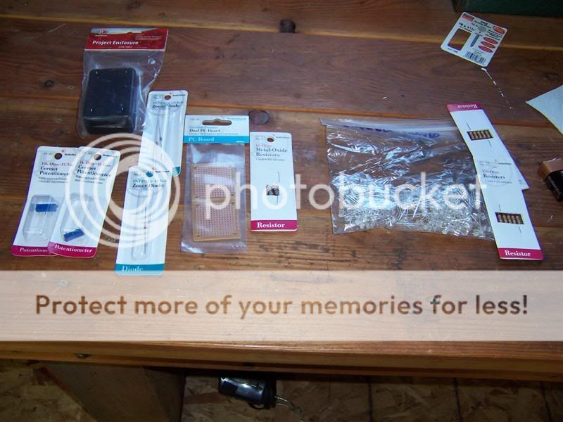
PN = radio shack part number
1 project box -optional PN 270-1801
1 circuit board PN 276-148
2 packages of 12Vz Zener diodes (4 diodes) PN 276-563
1 10K Ohm potentiometer PN 271-343
1 1K Ohm potentiometer PN 271-342
1 package of 10 Ohm 1W resistors PN 271-151
<span style="font-size:14pt;line-height:100%">Selecting your LEDs</span>
-this stuff you can go as crazy or as light as you want. these are calculated values, find one around that size.-
20 or so BLUE LEDs
470 ohm 1/4W resistors for strings of 1 BLUE LED
280 ohm 1/4W resistors for strings of 2 BLUE LEDs
120 ohm 1/4W resistors for strings of 3 BLUE LEDs
NOTE: resistance values will be different for different colored LEDs, these are for blue leds. You can go up to 6 LEDs if you choose red LEDs instead of blue, but you will need different resistors.
<span style="font-size:14pt;line-height:100%">More on LEDs</span>
for additional help see this site http://led.linear1.org/led.wiz. I do my calculations in calculator, but this could help you. The information they want is on the package. The voltage source will be 12V because of the zener diodes in this circuit.
<span style="font-size:14pt;line-height:100%">Building the controller</span>
So we start the project by placing components on the board and soldering them in place. you do not need a board, but it tidys it up.
have a friend read this to you as you look at the pictures below. it will make sence soon enough
1. Shave the board at this point on the edges to make it small enough to fit inside the box flat.
2. Set board on your work surface so the metal portions are facing downwards.
-mark your hot and return lines.
3. Draw across the top of the board, RED
4. Draw across the bottom of the board Black
-solder wires on top of board
5. tin and solder a red wire near the red line on left side
6. tin and solder a black wire near the black line
solder components on board.
7. Place a 10 ohm resistor lengthwise along the black line with one lead next to the black wire and solder in place. try to keep it small as possible.
8. solder reistor lead to black wire
9. place 4 zener diodes next to each other starting at the free edge of the resistor from black line on board to red line on board, with the line on the zener pointing towards the red line on the board. Solder in place
10. connect the ends of the zeners together and connect the 10ohm resistor to the non-line side of the zeners
11. mark the 10Kohm potentiometer with a C (it will be your coarse adjustment) and place it so it's first contact is on the red line, next to the red wire and it's adjustment screw is pointing off of the board.
note: the potentiometer will be used as a rheostat. We will call the pin closest to the dial "pin 1" next to the right, pin 2, and then the far right is pin 3.
12. when soldering the potentiometers, connect pins 1, 2, and red wire together
13. mark the 1K ohm potentiometer with a F (it will be your fine adjustment) and place it right next to the coarse adjust potentiometer.
14. connect pins 1 and 2 on F potentiometer and pin 3 on C potentometer together
15. connect pin 3 to the black line side of the zener diodes
-Output of circuit
16. Tin and connect a red wire to the black line on the zener (red line on board)
17. Tin and connect a black wire to the no line side of the zener diode.
18. run a marker down the edges of these 2 wires as you have a friend hold it. they will be your "signal" wires.
<span style="font-size:14pt;line-height:100%">Pictures
</span><span style="font-size:10pt;line-height:100%">Sorry, i don't have an actual picture of the circuit right now.. my car's packed full of stuff and i can't get to the circuit board.
</span><span style="font-size:14pt;line-height:100%">
Attachment 162
[attachment=268:attachment]
Attachment 163
Attachment 164
Attachment 165</span>
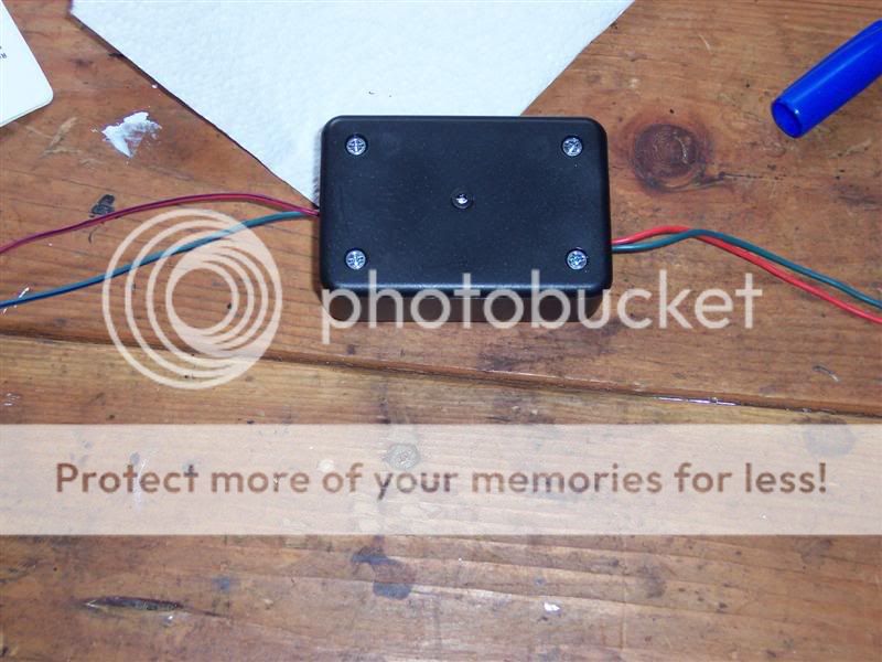
<span style="font-size:14pt;line-height:100%">Box it up</span>
Ok, here's what you do with the project box.
1. stick the board in
2. decide where you want your wires
3. drill holes
4. figure out how your board will lay inside
5. drill holes for adjusting the Coarse and Fine potentiometers
6. mount an LED with a 470 ohm resistor on the box so you can test it immediately
<span style="font-size:14pt;line-height:100%">Adjustments
</span>1. Turn the potentiometers completely counter clockwise.
2. Hook up power and return wires
3. Turn the music on LOUDLY I recommend Dr Crankenstein or Bass 305, but it's your pick choose something with BASS!!!
4. Slowly bring the potentiometers untll the LEDs flash brightly
note: this system will work for a large amplifier or a small head unit, use the coarse and the fine adjust.
note: if the LEDs go to bright, you will notice blue LEDs will start to turn slightly green. turn it down!!! You will damage the LEDs quickly.
Note: level 3 will not be as bright as the rest. It is only on 1/3 the time as the others.
5. bring it down a few turns with the fine adjustment to compensate for when your music goes way too loud.
<span style="font-size:14pt;line-height:100%">LEDs
</span>You can now go crazy with your LEDs. Your regulator will handle about 40 LEDs in 3 led strings, about 20 in 1 LED strings Mount them in your speakers, buy custom mounts and put them wherever you'd like.
Here's how it works... with blue LEDs.
a single LED will light at a low volume
2 LEDs will light at higher volumes
3 LEDs will light at really loud volumes
All LEDs will reach full brightness at the loudest setting.
1 blue LED needs 470 ohms of resistance on a 12V circuit
2 blue LEDS need 280 ohms of resistance on a 12V circuit
3 blue LEDS need 120 ohms of resistance on a 12V circuit
You do not need to use all 3 arrangements of LEDs, but it will be more interesting if you do.
Check this DIY out for info on how to mount LEDs in speakers
http://www.rdtiburon.com/index.php?showtopic=164
I hope this is enough. If you did it right your car should be flashing like a night club.... or maybe just dimly lighting with the music. You chose the ammount of LEDs you used.
This project allows you to take those LEDs you have laying around and make them dance to your music. it's a very simple project, it takes about 1 hour at most. I'm giving these instructions in the most basic manner possible. Please let me know if you do not understand them.
You can arrange them in any way you like...
Ideas:
1. Across the bottom of the back seat starting at the middle and as the music gets louder it goes towards the outside of the vehical
2. Project box lights up an LED, then when music gets louder, the rear speakers light up, and then the front at loudest volume
3. Put them in your shifter surround's hex nuts for a little light show.
4. Mount them in a straight line next to your sterio.
5. get creative on your dashboard or roof.
6. you can just make it so that level 3 is the only time you'll see light
<span style="font-size:14pt;line-height:100%">You will need the following beer:
</span>Corona w/ lime
<span style="font-size:14pt;line-height:100%">You will need the following tools:
</span>1 soldering gun
solder
black marker
red marker
you will also need some 20AWG or higher wire.
you will need to go to radio shack and get ripped off for:
<span style="font-size:14pt;line-height:100%">Parts for the LED controller</span>
PN = radio shack part number
1 project box -optional PN 270-1801
1 circuit board PN 276-148
2 packages of 12Vz Zener diodes (4 diodes) PN 276-563
1 10K Ohm potentiometer PN 271-343
1 1K Ohm potentiometer PN 271-342
1 package of 10 Ohm 1W resistors PN 271-151
<span style="font-size:14pt;line-height:100%">Selecting your LEDs</span>
-this stuff you can go as crazy or as light as you want. these are calculated values, find one around that size.-
20 or so BLUE LEDs
470 ohm 1/4W resistors for strings of 1 BLUE LED
280 ohm 1/4W resistors for strings of 2 BLUE LEDs
120 ohm 1/4W resistors for strings of 3 BLUE LEDs
NOTE: resistance values will be different for different colored LEDs, these are for blue leds. You can go up to 6 LEDs if you choose red LEDs instead of blue, but you will need different resistors.
<span style="font-size:14pt;line-height:100%">More on LEDs</span>
for additional help see this site http://led.linear1.org/led.wiz. I do my calculations in calculator, but this could help you. The information they want is on the package. The voltage source will be 12V because of the zener diodes in this circuit.
<span style="font-size:14pt;line-height:100%">Building the controller</span>
So we start the project by placing components on the board and soldering them in place. you do not need a board, but it tidys it up.
have a friend read this to you as you look at the pictures below. it will make sence soon enough
1. Shave the board at this point on the edges to make it small enough to fit inside the box flat.
2. Set board on your work surface so the metal portions are facing downwards.
-mark your hot and return lines.
3. Draw across the top of the board, RED
4. Draw across the bottom of the board Black
-solder wires on top of board
5. tin and solder a red wire near the red line on left side
6. tin and solder a black wire near the black line
solder components on board.
7. Place a 10 ohm resistor lengthwise along the black line with one lead next to the black wire and solder in place. try to keep it small as possible.
8. solder reistor lead to black wire
9. place 4 zener diodes next to each other starting at the free edge of the resistor from black line on board to red line on board, with the line on the zener pointing towards the red line on the board. Solder in place
10. connect the ends of the zeners together and connect the 10ohm resistor to the non-line side of the zeners
11. mark the 10Kohm potentiometer with a C (it will be your coarse adjustment) and place it so it's first contact is on the red line, next to the red wire and it's adjustment screw is pointing off of the board.
note: the potentiometer will be used as a rheostat. We will call the pin closest to the dial "pin 1" next to the right, pin 2, and then the far right is pin 3.
12. when soldering the potentiometers, connect pins 1, 2, and red wire together
13. mark the 1K ohm potentiometer with a F (it will be your fine adjustment) and place it right next to the coarse adjust potentiometer.
14. connect pins 1 and 2 on F potentiometer and pin 3 on C potentometer together
15. connect pin 3 to the black line side of the zener diodes
-Output of circuit
16. Tin and connect a red wire to the black line on the zener (red line on board)
17. Tin and connect a black wire to the no line side of the zener diode.
18. run a marker down the edges of these 2 wires as you have a friend hold it. they will be your "signal" wires.
<span style="font-size:14pt;line-height:100%">Pictures
</span><span style="font-size:10pt;line-height:100%">Sorry, i don't have an actual picture of the circuit right now.. my car's packed full of stuff and i can't get to the circuit board.
</span><span style="font-size:14pt;line-height:100%">
Attachment 162
[attachment=268:attachment]
Attachment 163
Attachment 164
Attachment 165</span>
<span style="font-size:14pt;line-height:100%">Box it up</span>
Ok, here's what you do with the project box.
1. stick the board in
2. decide where you want your wires
3. drill holes
4. figure out how your board will lay inside
5. drill holes for adjusting the Coarse and Fine potentiometers
6. mount an LED with a 470 ohm resistor on the box so you can test it immediately
<span style="font-size:14pt;line-height:100%">Adjustments
</span>1. Turn the potentiometers completely counter clockwise.
2. Hook up power and return wires
3. Turn the music on LOUDLY I recommend Dr Crankenstein or Bass 305, but it's your pick choose something with BASS!!!
4. Slowly bring the potentiometers untll the LEDs flash brightly
note: this system will work for a large amplifier or a small head unit, use the coarse and the fine adjust.
note: if the LEDs go to bright, you will notice blue LEDs will start to turn slightly green. turn it down!!! You will damage the LEDs quickly.
Note: level 3 will not be as bright as the rest. It is only on 1/3 the time as the others.
5. bring it down a few turns with the fine adjustment to compensate for when your music goes way too loud.
<span style="font-size:14pt;line-height:100%">LEDs
</span>You can now go crazy with your LEDs. Your regulator will handle about 40 LEDs in 3 led strings, about 20 in 1 LED strings Mount them in your speakers, buy custom mounts and put them wherever you'd like.
Here's how it works... with blue LEDs.
a single LED will light at a low volume
2 LEDs will light at higher volumes
3 LEDs will light at really loud volumes
All LEDs will reach full brightness at the loudest setting.
1 blue LED needs 470 ohms of resistance on a 12V circuit
2 blue LEDS need 280 ohms of resistance on a 12V circuit
3 blue LEDS need 120 ohms of resistance on a 12V circuit
You do not need to use all 3 arrangements of LEDs, but it will be more interesting if you do.
Check this DIY out for info on how to mount LEDs in speakers
http://www.rdtiburon.com/index.php?showtopic=164
I hope this is enough. If you did it right your car should be flashing like a night club.... or maybe just dimly lighting with the music. You chose the ammount of LEDs you used.
Thread Starter
Moderator
Joined: Feb 2009
Posts: 11,732
Likes: 5
From: Leesville, Louisiana
Vehicle: 2001 Hyundai Tiburon
rule.gif wine.gif
Yes. Any stock sterio deck or 10,000 watt quadraphonic hi-fi should work fine with this. Keep in mind that this would be the same as if you had hooked up another extremely small speaker. It won't make much of a difference if you fade your speakers 1 notch to the back.
the total power usage of this circuit should be around 1 - 2 watts max with duty cycles and all.

Thread Starter
Moderator
Joined: Feb 2009
Posts: 11,732
Likes: 5
From: Leesville, Louisiana
Vehicle: 2001 Hyundai Tiburon
Just keep in mind when you do this, the MOST efficient use of power comes with strings of 3 LEDs.
Here are some calculated values for maximum loads. Keep in mind that not all electronics are designed perfect and that these are MAX values.
40 strings of 3 (120 LEDs) .05W each string
17 strings of 2 (34 LEDs) .11W each string
10 strings of 1 (10 LEDs) .18W each string
Use strings of 1 sparingly. Keep the value of W lower then 2.0W in your setup.

Member
Joined: Mar 2006
Posts: 34
Likes: 0
From: Tinker AFB, Oklahoma City, OK
Just FYI.... I love the army now........ok not mre the=anthe chair force but oh well......this is great and when i get some cash flow ill be doing it.....plus i might be getting 15g's from a friends company....I cant wait smile.gif
Oh and about how much aporx. is this mod gonna run someone?
Oh and about how much aporx. is this mod gonna run someone?
Senior Member
Joined: Nov 2008
Posts: 2,881
Likes: 0
From: Huntsville, AL
Vehicle: 2001/Hyundai/Tiburon
<div class='quotetop'>QUOTE (DrivingTibNaked @ May 23 2006, 05:49 PM) <{POST_SNAPBACK}></div><div class='quotemain'>Just keep in mind when you do this, the MOST efficient use of power comes with strings of 3 LEDs.
Here are some calculated values for maximum loads. Keep in mind that not all electronics are designed perfect and that these are MAX values.
40 strings of 3 (120 LEDs) .05W each string
17 strings of 2 (34 LEDs) .11W each string
10 strings of 1 (10 LEDs) .18W each string
Use strings of 1 sparingly. Keep the value of W lower then 2.0W in your setup.</div>
What about setups where there is just one or a few LEDs (withouth this dancing LED setup)? Is it bad to hook those up like that? Or is it just when you use this box thing that you should try to adjust to the proper wattage?
SE
Thread Starter
Moderator
Joined: Feb 2009
Posts: 11,732
Likes: 5
From: Leesville, Louisiana
Vehicle: 2001 Hyundai Tiburon
^^^ Like I said, those were maximum values. You would be able to run 10 strings of 1 LED on this setup, or you could run 40 strings of 3. If you just want 1 LED, you'll be way under 2.0 watts, and putting alot less stress on the controller box then it can handle.
<div class='quotetop'>QUOTE (NoMaam-uron @ May 23 2006, 05:08 PM) <{POST_SNAPBACK}></div><div class='quotemain'>Oh and about how much aporx. is this mod gonna run someone?</div>
about $25 for the box with components and 1 LED and resistor from radioshack.... and however much you spend on LEDs.
<div class='quotetop'>QUOTE (tibby01 @ May 23 2006, 04:02 PM) <{POST_SNAPBACK}></div><div class='quotemain'>right, because you will be wasintg power through heat in the resistors, rather than light in leds.</div>
yeah, resistors are parasitic bastards that turn alot of electricity into heat.
I'd also like to say that this entire setup is at your own risk. Just make sure that you don't have any solder splashes connecting wires or something. smile.gif I can also make this a kit if you'd like: you'd just need to put the LEDs in your car, attatch resistors, wires, adust and let it rock.
Thread Starter
Moderator
Joined: Feb 2009
Posts: 11,732
Likes: 5
From: Leesville, Louisiana
Vehicle: 2001 Hyundai Tiburon
I've got alot of PMs about this project. You MUST build this box. If you hook up directly to the speakers you will blow up LEDs. This box manages all incomming signals from your amp/sterio and turns it into a usable voltage/current level for the LEDs. If you do not build the box, you will always blow up LEDs.
It's only a handful of components. I drew a picture to make it easier. I still havn't had a chance to get my camera and open my box.
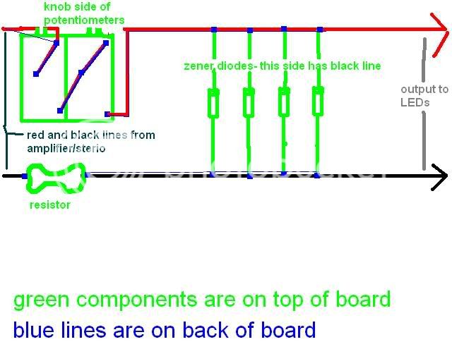
It's only a handful of components. I drew a picture to make it easier. I still havn't had a chance to get my camera and open my box.