
DIY on boost gauge install

Administrator

Joined: Oct 2002
Posts: 13,943
Likes: 0
From: ɯooɹpǝq ɹnoʎ
Vehicle: ǝdnoɔ sısǝuǝƃ
I had this bookmarked, hope it helps:
Source contributor: Projectx7
Disclaimer:
As with any DIY you assume full responsibility for what you do to your car and I am in no way liable for any damage that happens. In other wards do this DYI at your own risk.
Car: 2010 Genesis coupe R-Spec Edition
For all of my DIY the car model and trim will be a 2010 Genesis coupe R-Spec Edition most trims will be the same for most aspects but there is the possibility that things can be different on your trim vehicle that may require altering the DIY steps ect.
Materials:
Boost Gauge
- T-Fitting
- Vacuum Line
Mounting solution
Extra Wire
Double sided tape
Electrical tape
Zip ties
(2) Fuse Taps
Tools:
Small flat head screwdriver
Large Flat Head Screw Driver
Wire Cutters
Wire Stripper
Multimeter

Notes:
My setup consists of a Glowshift Tinted 7 Boost gauge and a Glowshift universal swivel pod so it will be specific to this setup and how I decided to mount mine yours will vary most likely but i will also talk about things generically.
Install:
Part 1: Prepping your gauge and Wires
1) Unpack your gauge and make sure all the content it is suppose to come with is included ect. With your boost gauge you most likely got the T-fitting and vacuum lines in the box which will be ample enough for the installation.
2) Next, extend the wires with enough length to easily make it to where it will be wired and connect the vacuum hose to the back of the gauge and mount the gauge into the pod.
Part 2: Mount your Gauge
I personally mounted mine on the steering Colum with a universal Glowshift Pod so this DIY will illustrate that.
1) First remove the swivel part off the Glowshift pod as it will not be needed in the installation.
2) Make sure your steering column is free of any detailing spray ect in other wards clean off the surface so you can get a good adhesion when we go to mount the gauge.
3) Lower the steering wheel all the way down so you can push through the vacuum line and wires through the top and get them out of the way. Now move your steering wheel back up and orientate the Pod how you like it. For me I orientated it so the piece that connects to the swivel is resting on the steering column, the rear of the pod is touching the silver bezel of your tach gauge, and the edge of the gauge pod is touching the steering column.

4) You should notice that your gauge can actually rest there without falling off which is great but let�s secure it. Now using your double sided tape cut off small pieces so that they will allow the gauge to mount to the contact points of the gauge pod and the steering wheel column/gauge bezel.

5) Now your gauge is mounted and you�re ready to proceed to the next step.

Part 3: Running the Vacuum Line
1) Look at your hood release latch and follow the cable straight back to the firewall, that black grommet is where our vacuum line will be running through to get the engine bay.

2) Using your small flat head screw driver pull the grommet out of the hole so you can work with it easier and allow you to have a little more leverage to get your line through.
3) As a tip using your small Flat head screwdriver show it into the grommet and pry open the hole so you can slide the vacuum line through with minimal effort.
4) Now locate your vacuum line in the engine bay and route it to the intake manifold where you see the white/green check valve this is where you will be splicing into to get your boost readings.

5) Looking at the Left Barb remove the grey hose with the check valve as a tip use your large flat head screw driver to help push the hose off.
6) Next you�re going to cut a small piece of vacuum tubing to stick on the left barb and be able to loop it so it does not pinch and connect it to one side of the T-fitting, the other side of the T-Fitting will be where the grey hose connects to continue back to the right barb, and finally the boost gauges vacuum line will connect to the output of the T-Fitting.

7) Now you want to secure the T-fitting and lines so it has a little bit of a Loop and does not deform and cause the hose to pinch as you can see in the picture so zip tie the T-fitting to the Left barb. Note on mine I used one of those twisty ties but it was only a temporary solution till I bought some real zip ties. Okay now for the Next step electrical!
Part 4: Wiring Your Gauge
Now for some reason everyone seems to get scared when doing electrical work and this is something you shouldn't be. Electrical work is actually very simple and has a definite result. As long as you follow the guidelines you will be fine and will cause no harm to yourself or your vehicle just be calm and follow the simple steps.
With my Gauge there are four wires to connect
With most electrical work be very careful of what you decide to splice into as a general rule never splice into a yellow wire since they are generally airbag wires this does not mean all yellow wires are airbag wires but some are so why not just avoid them, there�s plenty of choices for wires. Now there are many ways to wire these i will show you how i did mine and i opted to spice in to wires around the dash area for simplicity.
More importantly be sure to disconnect the Negative battery terminal for you and your cars safety!
Fuse Tap Method
1) Using two Fuse taps you will connect your constant wires to one fuse tap wire and your switched wires to another fuse tap. Install a 3 amp fuse on both fuse taps.
2) Next remove FOG LP(RR)on Fuse panel and insert your constant power fuse tap.
3) Remove your IGN/ESCL on fuse panel and insert your Switched power fuse tap
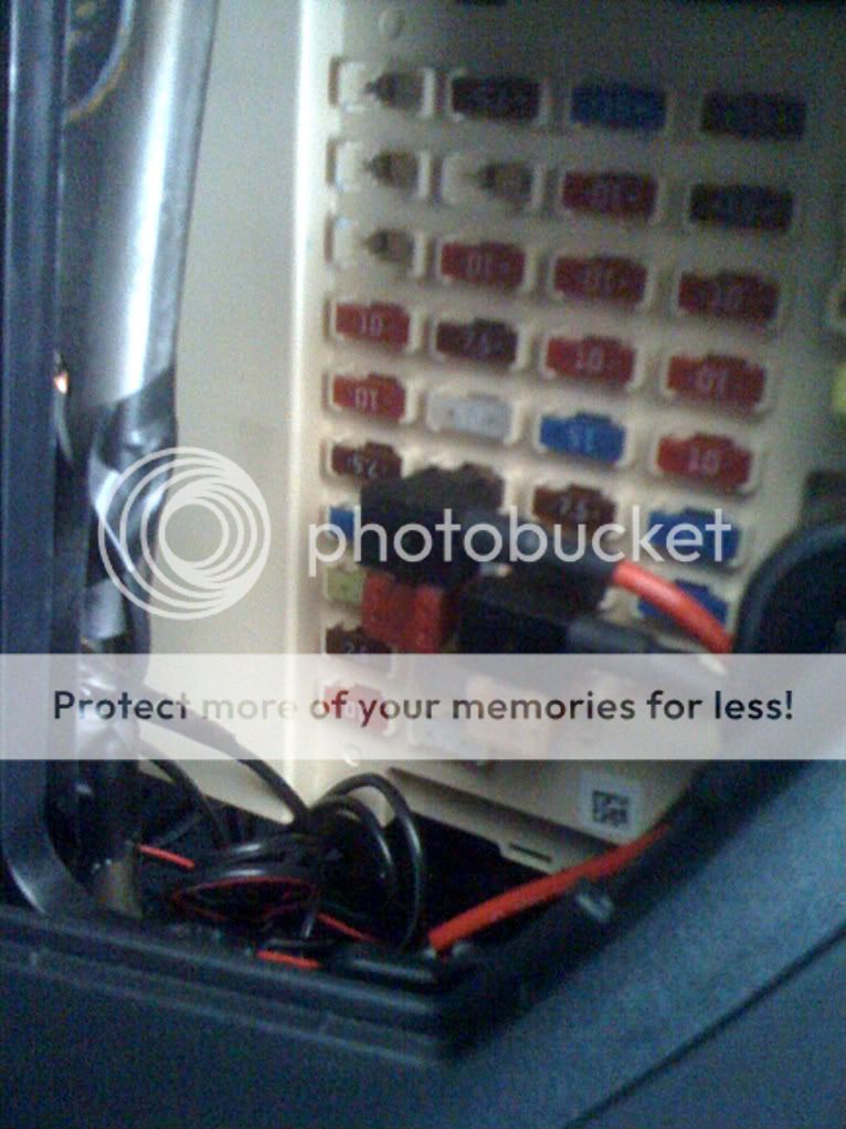
4) For your ground You have to attach it to any metal surface so look for a bolt/screw that you can remove and insert the wire with a proper clamp.
Splicing Method
1) Open up your dash area and route your wires into the center console. If your not sure on how to do this view this DIY:
DIY Center Console Removal

-Hooking up your Ground Lead
I chose to connect my ground wire by splicing into the ground wire of the cigarette lighter socket.
-Hooking up Your Constant Positive Lead
(Using your multimeter it must always read ~12v without your key in the ignition!)
For the Constant positive I spliced into the positive wire of the cigarette lighter socket.

-Hooking Up Your Switched Positive Lead
(This wire must read 0V with the key out of the ignition and when the key is in and switched to ACC it must read ~12V)
For this wire i chose a wire coming from the climate control harness since it was in the immediate area looking at the pin it was the red wire at the top right corner of the pin. Using my multimeter i confirmed that it only has voltage when in the Switched on position which is what you want. This is a part were certain trims may vary or may not so please use your multi meter to double check before just imitating my wiring job. It is not hard and is as easy as reading a digital watch. If you have questions on this process ask me questions I'll be happy to answer them.

Finalizing Installation:
Start up the car and make sure your gauge powers if it does not you may have messed up the wiring so shut off your car and open everything back up to make sure you do not have any lose connections or worse improperly wired the gauge.
Now assuming your gauge powers up take your car for a drive and don�t be afraid to WOT her she does love it but more importantly watch your boost gauge and make sure it�s working. If it is not then you must check to make sure your vacuum line is not pinched anywhere mainly where you connected the T- Fitting, where it comes through the firewall, or around where you mounted your gauge.
So now that everything is working correctly clean up your installation by zip tying any lose wires and the vacuum line in the engine bay so it doesn�t get in the way of anything hot.

Hopefully this helps all of you properly install your boost gauges as it�s a very important monitoring tool for your car!
Source contributor: Projectx7
Disclaimer:
As with any DIY you assume full responsibility for what you do to your car and I am in no way liable for any damage that happens. In other wards do this DYI at your own risk.
Car: 2010 Genesis coupe R-Spec Edition
For all of my DIY the car model and trim will be a 2010 Genesis coupe R-Spec Edition most trims will be the same for most aspects but there is the possibility that things can be different on your trim vehicle that may require altering the DIY steps ect.
Materials:
Boost Gauge
- T-Fitting
- Vacuum Line
Mounting solution
Extra Wire
Double sided tape
Electrical tape
Zip ties
(2) Fuse Taps
Tools:
Small flat head screwdriver
Large Flat Head Screw Driver
Wire Cutters
Wire Stripper
Multimeter
Notes:
My setup consists of a Glowshift Tinted 7 Boost gauge and a Glowshift universal swivel pod so it will be specific to this setup and how I decided to mount mine yours will vary most likely but i will also talk about things generically.
Install:
Part 1: Prepping your gauge and Wires
1) Unpack your gauge and make sure all the content it is suppose to come with is included ect. With your boost gauge you most likely got the T-fitting and vacuum lines in the box which will be ample enough for the installation.
2) Next, extend the wires with enough length to easily make it to where it will be wired and connect the vacuum hose to the back of the gauge and mount the gauge into the pod.
Part 2: Mount your Gauge
I personally mounted mine on the steering Colum with a universal Glowshift Pod so this DIY will illustrate that.
1) First remove the swivel part off the Glowshift pod as it will not be needed in the installation.
2) Make sure your steering column is free of any detailing spray ect in other wards clean off the surface so you can get a good adhesion when we go to mount the gauge.
3) Lower the steering wheel all the way down so you can push through the vacuum line and wires through the top and get them out of the way. Now move your steering wheel back up and orientate the Pod how you like it. For me I orientated it so the piece that connects to the swivel is resting on the steering column, the rear of the pod is touching the silver bezel of your tach gauge, and the edge of the gauge pod is touching the steering column.
4) You should notice that your gauge can actually rest there without falling off which is great but let�s secure it. Now using your double sided tape cut off small pieces so that they will allow the gauge to mount to the contact points of the gauge pod and the steering wheel column/gauge bezel.
5) Now your gauge is mounted and you�re ready to proceed to the next step.
Part 3: Running the Vacuum Line
1) Look at your hood release latch and follow the cable straight back to the firewall, that black grommet is where our vacuum line will be running through to get the engine bay.
2) Using your small flat head screw driver pull the grommet out of the hole so you can work with it easier and allow you to have a little more leverage to get your line through.
3) As a tip using your small Flat head screwdriver show it into the grommet and pry open the hole so you can slide the vacuum line through with minimal effort.
4) Now locate your vacuum line in the engine bay and route it to the intake manifold where you see the white/green check valve this is where you will be splicing into to get your boost readings.
5) Looking at the Left Barb remove the grey hose with the check valve as a tip use your large flat head screw driver to help push the hose off.
6) Next you�re going to cut a small piece of vacuum tubing to stick on the left barb and be able to loop it so it does not pinch and connect it to one side of the T-fitting, the other side of the T-Fitting will be where the grey hose connects to continue back to the right barb, and finally the boost gauges vacuum line will connect to the output of the T-Fitting.
7) Now you want to secure the T-fitting and lines so it has a little bit of a Loop and does not deform and cause the hose to pinch as you can see in the picture so zip tie the T-fitting to the Left barb. Note on mine I used one of those twisty ties but it was only a temporary solution till I bought some real zip ties. Okay now for the Next step electrical!
Part 4: Wiring Your Gauge
Now for some reason everyone seems to get scared when doing electrical work and this is something you shouldn't be. Electrical work is actually very simple and has a definite result. As long as you follow the guidelines you will be fine and will cause no harm to yourself or your vehicle just be calm and follow the simple steps.
With my Gauge there are four wires to connect
With most electrical work be very careful of what you decide to splice into as a general rule never splice into a yellow wire since they are generally airbag wires this does not mean all yellow wires are airbag wires but some are so why not just avoid them, there�s plenty of choices for wires. Now there are many ways to wire these i will show you how i did mine and i opted to spice in to wires around the dash area for simplicity.
More importantly be sure to disconnect the Negative battery terminal for you and your cars safety!
Fuse Tap Method
1) Using two Fuse taps you will connect your constant wires to one fuse tap wire and your switched wires to another fuse tap. Install a 3 amp fuse on both fuse taps.
2) Next remove FOG LP(RR)on Fuse panel and insert your constant power fuse tap.
3) Remove your IGN/ESCL on fuse panel and insert your Switched power fuse tap
4) For your ground You have to attach it to any metal surface so look for a bolt/screw that you can remove and insert the wire with a proper clamp.
Splicing Method
1) Open up your dash area and route your wires into the center console. If your not sure on how to do this view this DIY:
DIY Center Console Removal
-Hooking up your Ground Lead
I chose to connect my ground wire by splicing into the ground wire of the cigarette lighter socket.
-Hooking up Your Constant Positive Lead
(Using your multimeter it must always read ~12v without your key in the ignition!)
For the Constant positive I spliced into the positive wire of the cigarette lighter socket.
-Hooking Up Your Switched Positive Lead
(This wire must read 0V with the key out of the ignition and when the key is in and switched to ACC it must read ~12V)
For this wire i chose a wire coming from the climate control harness since it was in the immediate area looking at the pin it was the red wire at the top right corner of the pin. Using my multimeter i confirmed that it only has voltage when in the Switched on position which is what you want. This is a part were certain trims may vary or may not so please use your multi meter to double check before just imitating my wiring job. It is not hard and is as easy as reading a digital watch. If you have questions on this process ask me questions I'll be happy to answer them.
Finalizing Installation:
Start up the car and make sure your gauge powers if it does not you may have messed up the wiring so shut off your car and open everything back up to make sure you do not have any lose connections or worse improperly wired the gauge.
Now assuming your gauge powers up take your car for a drive and don�t be afraid to WOT her she does love it but more importantly watch your boost gauge and make sure it�s working. If it is not then you must check to make sure your vacuum line is not pinched anywhere mainly where you connected the T- Fitting, where it comes through the firewall, or around where you mounted your gauge.
So now that everything is working correctly clean up your installation by zip tying any lose wires and the vacuum line in the engine bay so it doesn�t get in the way of anything hot.
Hopefully this helps all of you properly install your boost gauges as it�s a very important monitoring tool for your car!
Junior Member

Joined: Jan 2012
Posts: 9
Likes: 0
From: Kanata, Ontario
Vehicle: 2011 Hyundai Genesis Coupe 2.0T
This is the DIY I used, just read over it a couple times first, and take your time. Make sure no tubing gets pinched at all anywhere, and everything is tight. Feeding the tube through the firewall grommet was the most annoying thing