Perfect Power Smt-6 Wiring Diagrams Guide
 04-03-2006, 04:42 PM
#1
http://www.hyundaiaftermarket.org/images/vendor1.png

Thread Starter
Join Date: Mar 2006
Location: Vancouver, BC, Canada
Posts: 2,178
Likes: 0
Received 0 Likes
on
0 Posts
Vehicle: 01 Tiburon
I have spent sometime learning the functions and applications of the SMT-6. I have played with the wires; reconnect, disconnet, measured voltages, etc, studied the manuals, notes and familiarized the software. Each wires has a certain function.. you can wire it up with only the basic function used or have it do other advanced functions that will help you greatly in tuning. This guide is meant to help those who will or already have an SMT-6 to install it very easily
I give props to monsieur denis (denisst99) for tips and support. More power to you man...

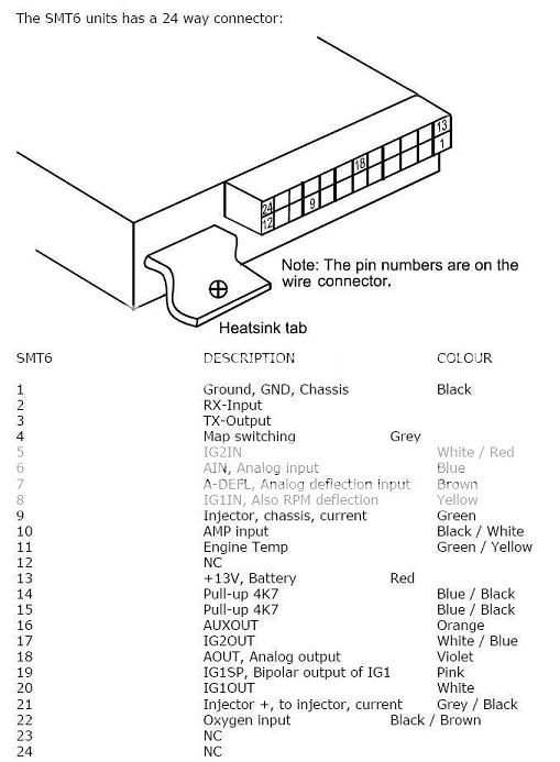
Here is the SMT-6 wiring pin out (note: the first row has pin #'s 1 - 12 and the second row is from 13 - 24):

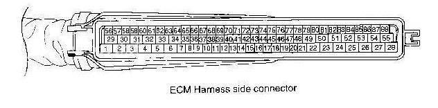
This is the ECU connector pin outs:
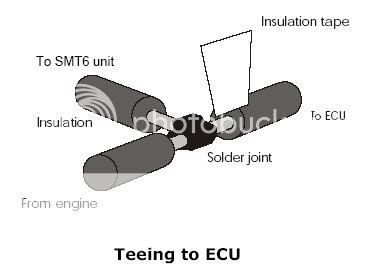
It's always best to solder the connections, it provides a better and realiable conduction. If possible, stay away from wire taps (i know, its easy but it's not that reliable plus it's bulky). Either shrink wrap or use and and electrical tape to insulate/cover the bare wire. It gets pretty cramped with wires and etc under the dash so, any unused wires should be cut (until non of the copper conduction is showing) or insulated, it will prevent shortage and false readings.
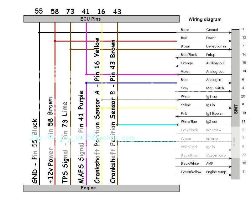
The wiring diagram below is the when an SMT-6 is used only to manipulate the MAF signal based on the RPM and TPS. In other words it's wired like a SAFC.
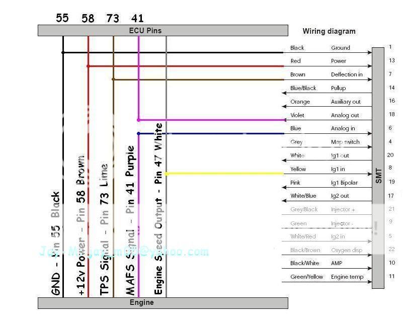
This is the basic SMT-6 wiring. Now, we can advance or retard the timing.
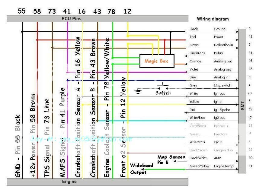
The diagram below is what i call the Not-So-Basic-Anymore Smt-6 wiring diagram. With this, you can view or log the stock narrowband o2 afr and the coolant temperature.
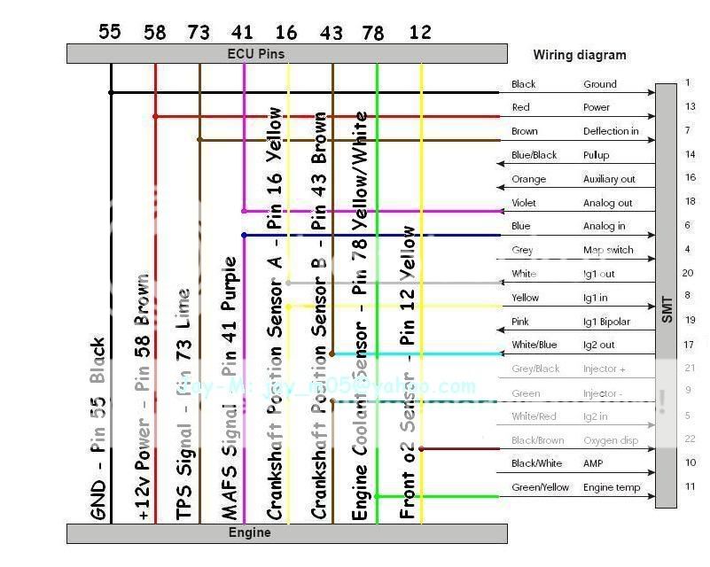
In the software, the coolant temperarute (ENG Temp) has to be calibrated to the car's spec to be able to show the right values. Read the manual for more info on this. You can PM me if you need more assistance on this matter.
Here's mine:
TL 0 0 237
TH 13 80 66
That calibration shows the coolant temperature in degrees celcius (i'm Canadian, it easier and makes more sense). It's up to you if you want yours calibrated to farenheit.
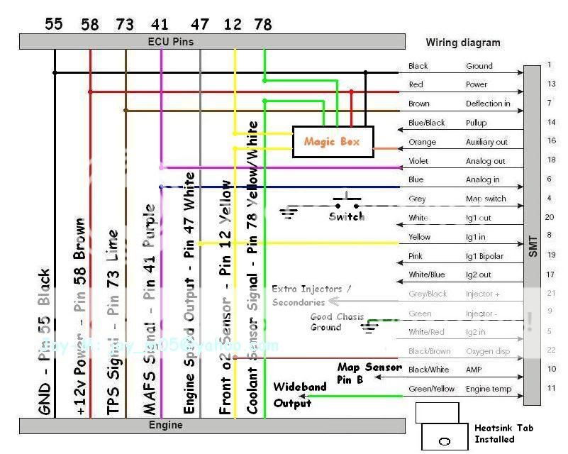
Now, let's get to another application of the SMT-6: Turbo Fueler or Extra Injector(s). The wiring diagram is as follows:
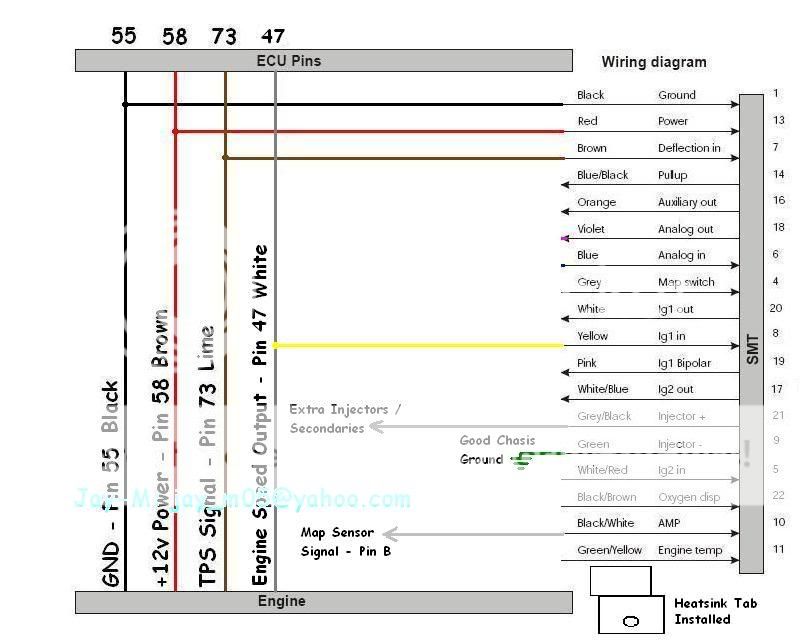
A few notes:
- Pin # 9 (green) wire of the SMT-6 has to be connected to a very good chasis ground
- The heatsink tab maybe installed to for added protection against heat (injector driver current)
Map Sensor wiring diagram:
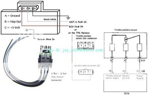
A 2 bar map sensor is good for max 15 psi function and a 3 bar map sensor is good up to 30 psi function. The software has to be calibrated to show the proper psi or bar. Read the manual on more info about this or PM me.
I have a 3 bar and it's shows in psi on my software. My calibration is shown below:
AL 0 -5 68
AH 15 28 250
Extra Injector(s) wiring diagram:
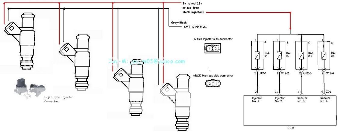
It's pretty straightforward no explanations needed here
As for more advanced stuff, here is how i got mine connected at the moment:
Added Functions:
- Logs my wideband AFR
- Can switch to a whole different (fuel) map with a press of a switch (don't need the laptop anymore)
- I can see my boost
- " Magic box " is activated by certain setpoints. Thanks denis!!! you can prolly guess it's function by just looking on how it's connected.
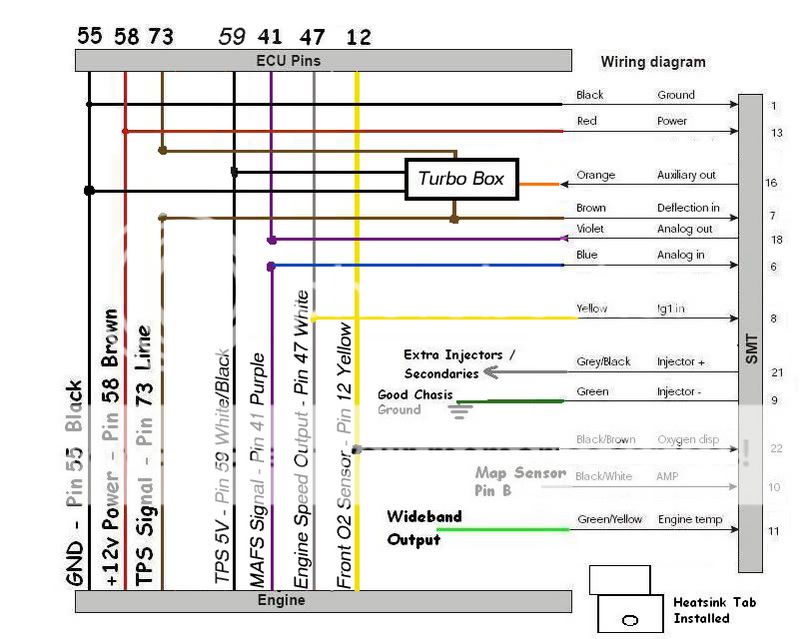
Below is a little peek to my next setup:
New Added Functions:
- Extra injectors
- Still can manipulate the MAF signal to give me a "soft" transition from low/no boost to boost
At the cost of:
- Lose the ignition advance or retard function
UPDATE:
Thanks to nate704...
This is how denis' turbo box version 2 is connected! This wiring diagram also shows the secondary injectors' connections
Hopefully this will help you fellas... If any one has seen any errors or question, please PM me or reply on this thread.
Thanks
I give props to monsieur denis (denisst99) for tips and support. More power to you man...
Here is the SMT-6 wiring pin out (note: the first row has pin #'s 1 - 12 and the second row is from 13 - 24):
This is the ECU connector pin outs:
It's always best to solder the connections, it provides a better and realiable conduction. If possible, stay away from wire taps (i know, its easy but it's not that reliable plus it's bulky). Either shrink wrap or use and and electrical tape to insulate/cover the bare wire. It gets pretty cramped with wires and etc under the dash so, any unused wires should be cut (until non of the copper conduction is showing) or insulated, it will prevent shortage and false readings.
The wiring diagram below is the when an SMT-6 is used only to manipulate the MAF signal based on the RPM and TPS. In other words it's wired like a SAFC.
This is the basic SMT-6 wiring. Now, we can advance or retard the timing.
The diagram below is what i call the Not-So-Basic-Anymore Smt-6 wiring diagram. With this, you can view or log the stock narrowband o2 afr and the coolant temperature.
In the software, the coolant temperarute (ENG Temp) has to be calibrated to the car's spec to be able to show the right values. Read the manual for more info on this. You can PM me if you need more assistance on this matter.
Here's mine:
TL 0 0 237
TH 13 80 66
That calibration shows the coolant temperature in degrees celcius (i'm Canadian, it easier and makes more sense). It's up to you if you want yours calibrated to farenheit.
Now, let's get to another application of the SMT-6: Turbo Fueler or Extra Injector(s). The wiring diagram is as follows:
A few notes:
- Pin # 9 (green) wire of the SMT-6 has to be connected to a very good chasis ground
- The heatsink tab maybe installed to for added protection against heat (injector driver current)
Map Sensor wiring diagram:
A 2 bar map sensor is good for max 15 psi function and a 3 bar map sensor is good up to 30 psi function. The software has to be calibrated to show the proper psi or bar. Read the manual on more info about this or PM me.
I have a 3 bar and it's shows in psi on my software. My calibration is shown below:
AL 0 -5 68
AH 15 28 250
Extra Injector(s) wiring diagram:
It's pretty straightforward no explanations needed here
As for more advanced stuff, here is how i got mine connected at the moment:
Added Functions:
- Logs my wideband AFR
- Can switch to a whole different (fuel) map with a press of a switch (don't need the laptop anymore)
- I can see my boost
- " Magic box " is activated by certain setpoints. Thanks denis!!! you can prolly guess it's function by just looking on how it's connected.
Below is a little peek to my next setup:
New Added Functions:
- Extra injectors
- Still can manipulate the MAF signal to give me a "soft" transition from low/no boost to boost
At the cost of:
- Lose the ignition advance or retard function
UPDATE:
Thanks to nate704...
This is how denis' turbo box version 2 is connected! This wiring diagram also shows the secondary injectors' connections
Hopefully this will help you fellas... If any one has seen any errors or question, please PM me or reply on this thread.
Thanks
 04-03-2006, 09:28 PM
#2
Senior Member

Join Date: Mar 2006
Location: Tampa/St Petersburg
Posts: 4,334
Likes: 0
Received 0 Likes
on
0 Posts
Vehicle: Turbocharged 2001 Hyundai Tiburon
NICE writup, everything you need to know about the smt-6, and even how to connect them. good stuff. Later ill check it against the diagrams i have to make sure they match up. ill make sure denisst99 sees this too as he works for perfect power and will be able to verify everything.
 04-03-2006, 10:10 PM
#5
http://www.hyundaiaftermarket.org/images/vendor1.png

Join Date: May 2002
Location: Canada
Posts: 1,500
Likes: 0
Received 0 Likes
on
0 Posts
Vehicle: x3 accent gk tiburon santa fe
i'll try to compare it against the wiring i've made
i might be able to put the one with the ignition fix if i put my hands on it
please note, on the SMT-6 box drawing there's an error, it's supposed to have two rows of 12 pins but if you look carefully you'l lsee 2 rows of 13 pins,please take note of this if you count the pins to do the wiring
i might be able to put the one with the ignition fix if i put my hands on it
please note, on the SMT-6 box drawing there's an error, it's supposed to have two rows of 12 pins but if you look carefully you'l lsee 2 rows of 13 pins,please take note of this if you count the pins to do the wiring
04-03-2006, 10:41 PM
#6
Senior Member
Join Date: Mar 2006
Location: Tampa/St Petersburg
Posts: 4,334
Likes: 0
Received 0 Likes
on
0 Posts
Vehicle: Turbocharged 2001 Hyundai Tiburon
/\ haha i spotted that 4 ya! took you a while before you figured out what i was saying lol. Also the 18 is way off, its where the 21 should be if you count down from 24
04-04-2006, 01:08 AM
#7
http://www.hyundaiaftermarket.org/images/vendor1.png
Join Date: May 2002
Location: Canada
Posts: 1,500
Likes: 0
Received 0 Likes
on
0 Posts
Vehicle: x3 accent gk tiburon santa fe
yup props to you Alex ;-)
i always go by pin number not location
btw, pin numbers are indicated on connector, so it'S quite easy to figure out
but i did notice them about the error
i always go by pin number not location
btw, pin numbers are indicated on connector, so it'S quite easy to figure out
but i did notice them about the error
 04-04-2006, 03:38 AM
#9
http://www.hyundaiaftermarket.org/images/vendor1.png
Thread Starter
Join Date: Mar 2006
Location: Vancouver, BC, Canada
Posts: 2,178
Likes: 0
Received 0 Likes
on
0 Posts
Vehicle: 01 Tiburon
QUOTE (Patreezy @ Apr 3 2006, 10:49 PM)
I love you Jay....
QUOTE (faithofadragon @ Apr 3 2006, 11:07 PM)
me and pat BOTH love you jay
I love you to fellas... that's why i took time make this and shared it to you'all
QUOTE (Denisst99 @ Apr 3 2006, 11:10 PM)
please note, on the SMT-6 box drawing there's an error, it's supposed to have two rows of 12 pins but if you look carefully you'l lsee 2 rows of 13 pins,please take note of this if you count the pins to do the wiring
QUOTE (Alex01tib @ Apr 3 2006, 11:41 PM)
/\ haha i spotted that 4 ya! took you a while before you figured out what i was saying lol. Also the 18 is way off, its where the 21 should be if you count down from 24
Yes, i did notice that and i did put a note about it to point the error to others.
I had some time to fix it tonight, here is the corrected version, it is uploaded on the main post as well