Diy: Starter Button (version 2.0)
 08-14-2007, 10:58 PM
#1
Senior Member
Thread Starter

Join Date: Jan 2007
Location: Central PA
Posts: 147
Likes: 0
Received 0 Likes
on
0 Posts
Well I didn't want to keep jumping onto the old DIY, so I decided to make another topic and post how I did my starter button (using nothing more then switches from a local store). I won't have all the pictures for the basic things and some others at this point, I want to do some more things so I will update with exact pictures of everything soon.
Parts Needed:
-5 Pin Relay socket (bought from Parts-Express- Part Number:330-075)
-30A SPDT Relay (bought from Parts-Express- Part Number:330-070)
-12V On/Off Switch
-12V Momentary Switch
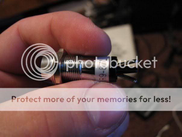
-LED light (Optional)
-Some Wire (I used 18 gauge and some 12 gauge as well).
-Wire Crimp Connectors
- 4 Bottles of water (I'm not legally able to drink and I drink water like a fish hehe).
Pictures of the parts I used:


Tools Required:
-Wire clippers
-Screwdriver
-Wire crimps
-Electrical Tape
-Soldering Iron (Optional)
Steps: (ALWAYS disconnect the negative wire from the battery before embarking on this)
1. Remove bottom dash cover
2. Remove steering column cover
3. Remove shifter knob/boot/cover and console cover.
4. Mount LED and Momentary switch on cover.
Originally I put the switch in the cigarette lighter, this however I didn't like. I always had to lean forward to start my car and in my job, I'm always starting/stopping, so it was annoying.
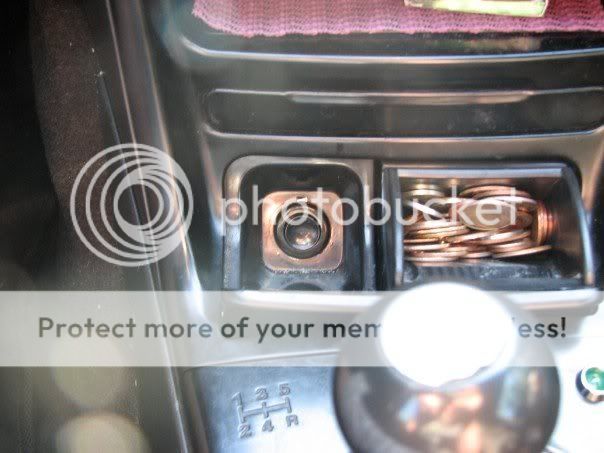

I mounted the push button on the left side right in the middle of where the gear pattern was, then mounted the LED on the right side.
5. Mount 12V On/Off switch

I'm still working on the "flush mount" to that switch, it looks amazingly clean when it is flush, so make sure you put it somewhere you think you would like (dead plastics on the dash perhaps?).
6. Run wires from the 12V Constant to the 12V On/Off, then to the LED, then to the Momentary.
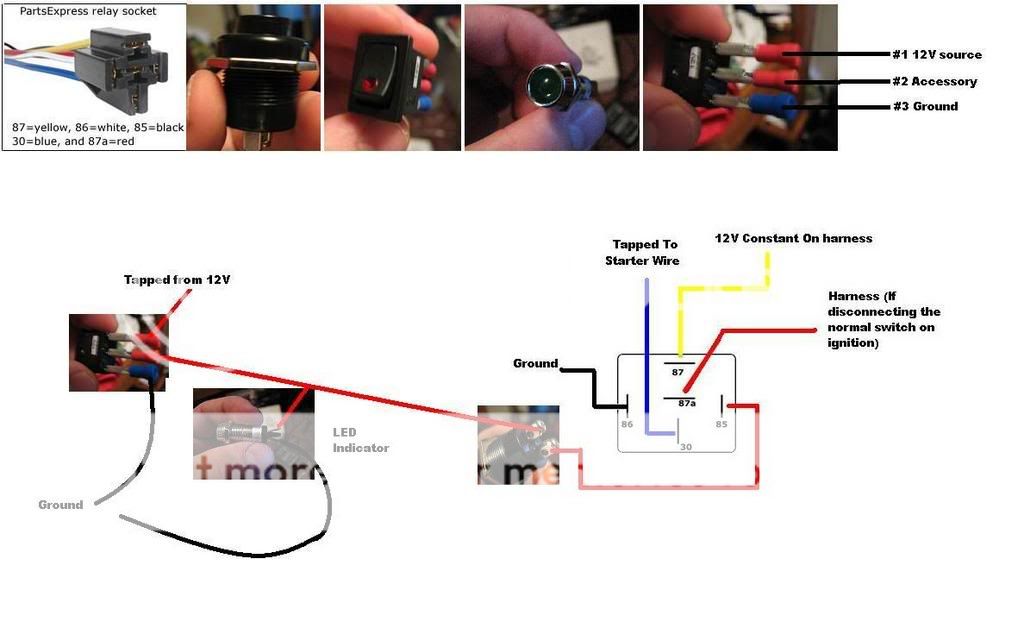
I made this diagram as a quick reference to help me along the way.
I used the cigarette lighters as my 12V constant. I ran this to the 12V switch at the dash, then ran the accessory from the 12V back to the LED (cut the wire, stripped it and the other end, soldered to the other cut wire, crimped a connector on and then to the LED (because the LED uses a positive and a ground, which means there isn't an accessory plug)), then I ran this to the momentary switch.
Now heres the fun part.
7. Run a wire out the other terminal from the momentary switch, and run this to pin 85 of your relay socket (black wire on the socket).
8. Run a ground wire from pin 86 (the white wire of the relay socket) and hook it to a good ground (there are plenty of spots under there.)
9. Underneath the steering column you will have to look up. Up in there you will see a bunch wires connected to a harness. These may be connected by a cable to, if you want more room, reach up and cut the cable tie. I pull just about all these wires down and disconnected them all just to be sure I disconnect the right ones. Now look at the back of your ignition, there will be a set of wires coming out and then down through the column and you should trace it to a plug. The plug will then connect to a harness. Disconnect this harness.
Now my car is a 2001 Tiburon, the colors change from 97-98 99 2000 2001, so unless you are doing this to a 2001 Tiburon, you better check the colors of wires (go to www.bulldogsecurity.com)
On the 2001 Tiburon the colors are as follows (on the engine side of the harness, meaning, the side that IS NOT coming from the ignition).
Gray = Starter
Blue = 12V constant
10. Run pin 30 (blue wire) to the gray starter wire (tap into the gray wire, or cut/strip/splice it in (wouldn't recommend that though)).
11. Run pin 87 (yellow wire) to the 12V constant of the car (blue wire from the engine side (of a 2001 Tib)).
12. Tape off Pin 87a (red wire of the relay socket). I believe if you want, you can cut the 12V constant from the starter, connect that to pin 30, then run pin 87a to the cut wire from the switch, but I'm not positive on that (yet).
13. Connect the relay socket with a relay.
14. TEST IT OUT BEFORE YOU PUT EVERYTHING BACK TOGETHER. (Make sure you connect the battery back on to test it fing02.gif.) Note that I also checked things almost every step to be sure so I didn't have to backtrack EVERYTHING. Make sure you connect your relay socket to the right wires!
15. If everything works right, when your 12V on/off is off, the LED should be off and the momentary switch WILL NOT work. I added this to mine so no-one messes with it while I'm driving. When you switch your On/Off to ON, the LED should turn on, showing that your momentary switch is getting power. If this is true, when you press the momentary switch in, your car should start up! smile.gif
16. Cable tie everything up (I'm sure you don't want loose wires flailing around!)
17. Reassemble your interior (dash, shifter cover/boot/knob/console).
18. Test out your new switch!
Hopefully this can help anyone else who is looking to make this and not want to fork $35-40 for a switch that can be replaced using a different, $1-$2, momentary switch.
Finished project (After remounting the momentary and changing the LED to a red one)


If anyone would like that diagram just tell me and I'll send it to you in a bigger printable version. Hopefully this helps some people out!
Parts Needed:
-5 Pin Relay socket (bought from Parts-Express- Part Number:330-075)
-30A SPDT Relay (bought from Parts-Express- Part Number:330-070)
-12V On/Off Switch
-12V Momentary Switch
-LED light (Optional)
-Some Wire (I used 18 gauge and some 12 gauge as well).
-Wire Crimp Connectors
- 4 Bottles of water (I'm not legally able to drink and I drink water like a fish hehe).
Pictures of the parts I used:
Tools Required:
-Wire clippers
-Screwdriver
-Wire crimps
-Electrical Tape
-Soldering Iron (Optional)
Steps: (ALWAYS disconnect the negative wire from the battery before embarking on this)
1. Remove bottom dash cover
2. Remove steering column cover
3. Remove shifter knob/boot/cover and console cover.
4. Mount LED and Momentary switch on cover.
Originally I put the switch in the cigarette lighter, this however I didn't like. I always had to lean forward to start my car and in my job, I'm always starting/stopping, so it was annoying.
I mounted the push button on the left side right in the middle of where the gear pattern was, then mounted the LED on the right side.
5. Mount 12V On/Off switch
I'm still working on the "flush mount" to that switch, it looks amazingly clean when it is flush, so make sure you put it somewhere you think you would like (dead plastics on the dash perhaps?).
6. Run wires from the 12V Constant to the 12V On/Off, then to the LED, then to the Momentary.
I made this diagram as a quick reference to help me along the way.
I used the cigarette lighters as my 12V constant. I ran this to the 12V switch at the dash, then ran the accessory from the 12V back to the LED (cut the wire, stripped it and the other end, soldered to the other cut wire, crimped a connector on and then to the LED (because the LED uses a positive and a ground, which means there isn't an accessory plug)), then I ran this to the momentary switch.
Now heres the fun part.
7. Run a wire out the other terminal from the momentary switch, and run this to pin 85 of your relay socket (black wire on the socket).
8. Run a ground wire from pin 86 (the white wire of the relay socket) and hook it to a good ground (there are plenty of spots under there.)
9. Underneath the steering column you will have to look up. Up in there you will see a bunch wires connected to a harness. These may be connected by a cable to, if you want more room, reach up and cut the cable tie. I pull just about all these wires down and disconnected them all just to be sure I disconnect the right ones. Now look at the back of your ignition, there will be a set of wires coming out and then down through the column and you should trace it to a plug. The plug will then connect to a harness. Disconnect this harness.
Now my car is a 2001 Tiburon, the colors change from 97-98 99 2000 2001, so unless you are doing this to a 2001 Tiburon, you better check the colors of wires (go to www.bulldogsecurity.com)
On the 2001 Tiburon the colors are as follows (on the engine side of the harness, meaning, the side that IS NOT coming from the ignition).
Gray = Starter
Blue = 12V constant
10. Run pin 30 (blue wire) to the gray starter wire (tap into the gray wire, or cut/strip/splice it in (wouldn't recommend that though)).
11. Run pin 87 (yellow wire) to the 12V constant of the car (blue wire from the engine side (of a 2001 Tib)).
12. Tape off Pin 87a (red wire of the relay socket). I believe if you want, you can cut the 12V constant from the starter, connect that to pin 30, then run pin 87a to the cut wire from the switch, but I'm not positive on that (yet).
13. Connect the relay socket with a relay.
14. TEST IT OUT BEFORE YOU PUT EVERYTHING BACK TOGETHER. (Make sure you connect the battery back on to test it fing02.gif.) Note that I also checked things almost every step to be sure so I didn't have to backtrack EVERYTHING. Make sure you connect your relay socket to the right wires!
15. If everything works right, when your 12V on/off is off, the LED should be off and the momentary switch WILL NOT work. I added this to mine so no-one messes with it while I'm driving. When you switch your On/Off to ON, the LED should turn on, showing that your momentary switch is getting power. If this is true, when you press the momentary switch in, your car should start up! smile.gif
16. Cable tie everything up (I'm sure you don't want loose wires flailing around!)
17. Reassemble your interior (dash, shifter cover/boot/knob/console).
18. Test out your new switch!
Hopefully this can help anyone else who is looking to make this and not want to fork $35-40 for a switch that can be replaced using a different, $1-$2, momentary switch.
Finished project (After remounting the momentary and changing the LED to a red one)
If anyone would like that diagram just tell me and I'll send it to you in a bigger printable version. Hopefully this helps some people out!
 08-14-2007, 11:23 PM
#2
Senior Member

Join Date: Mar 2002
Location: Los Lunas, New Mexico, USA.
Posts: 34,642
Likes: 0
Received 0 Likes
on
0 Posts
Vehicle: 2001 Hyundai Tiburon, 2004 Kia Sorento, 2010 Kia Soul
I'm actually pretty impressed. Very good job for a first DIY.
A few comments.
1. I'm not sure, I thought I read the whole thing, but why 2 switches?
2. On the RD2, the FOG LIGHT switch on the left. You can buy a second one, and mount it upside down at the top. I think that would look VERY nice.
BTW, go ahead with the bigger clearer versions of the pics.
A few comments.
1. I'm not sure, I thought I read the whole thing, but why 2 switches?
2. On the RD2, the FOG LIGHT switch on the left. You can buy a second one, and mount it upside down at the top. I think that would look VERY nice.
BTW, go ahead with the bigger clearer versions of the pics.
 08-14-2007, 11:37 PM
#4
Senior Member
Thread Starter
Join Date: Jan 2007
Location: Central PA
Posts: 147
Likes: 0
Received 0 Likes
on
0 Posts
In response to REDZMAN:
Thanks REDZMAN!
I used two switches because I wanted to be able to switch off the LED, and it also shows that the momentary switch is getting 12V power (so that you know if something is going on before or after if for some reason the push button would fail). Also, it would be harder for someone else to just jump in and press the button (a friend messing around could jump in and press it and grind my starter (I have stupid friends LOL)). I'm thinking about replacing that bottom cover on my dash (because it was already messed up) and mounting it how you said. It was an idea at first, but I didn't have the switches readily available and I wanted to get this baby up and going with the small amount of time I had. I'll definitely post up when I move it there though!
In response to tibby01:
Haha. This definitely isn't something for everyone. It was more or less one of those "Hmm...what can I do to my car to set it off a little..." kinda things. Thanks though! Hopefully it helps some people out!
Hopefully this is a bigger pic of the diagram!
Thanks for the replies guys!
08-15-2007, 01:47 AM
#5
Moderator


I would have done 2 things differently.
1. The ground on the 2nd switch has no purpose. It's just a waste of a wire.
2. The crimp connectors you used are not ment for automotive applications. They're not fully insulated. I would like to suggest these insulated disconnects.

http://www.radioshack.com/product/index.js...rentPage=search
Using those connectors, assuming that you left your starter switch in the circuit, you could have installed this relay instead of special ordering a relay and a connector for it. http://www.radioshack.com/product/index.js...rentPage=search
Great DIY man. Props!
1. The ground on the 2nd switch has no purpose. It's just a waste of a wire.
2. The crimp connectors you used are not ment for automotive applications. They're not fully insulated. I would like to suggest these insulated disconnects.
http://www.radioshack.com/product/index.js...rentPage=search
Using those connectors, assuming that you left your starter switch in the circuit, you could have installed this relay instead of special ordering a relay and a connector for it. http://www.radioshack.com/product/index.js...rentPage=search
Great DIY man. Props!
08-15-2007, 07:59 AM
#6
Senior Member

Join Date: Jul 2004
Location: Eau Claire, WI
Posts: 5,155
Likes: 0
Received 0 Likes
on
0 Posts
Vehicle: 97 Tib
That was something that always stopped me from doing this mod. If you mounted the start button somewhere accessible to both passenger/driver, how could you have a safety on it so that it can't be engaged while the car is running? There are people that would get in and just push that thing for fun, not thinking about the consequences of grinding the starter.
Is there a way to do that without using a secondary switch like you did?
The only way I would do this mod is if I could make it totally functional and keyless. I would want a key fob and a nice alarm so that I could still have the ON and ACC mode, and keyless remote entry/start, and I would make it so the start button when pushed while the car was running would act as the stop button also.
It would have to be some sort of system where the start button would not engage unless the key fob was inside the car (or if it was engaged from the remote start on the key fob in the first place) This is the kind of system they have on the luxury vehicles. I wonder if anyone makes a universal kit that would do that?
**ooooh, read this: http://www.edmunds.com/ownership/audio/art...51/article.html
Having a start button is really cool, but its so pointless if you have to use the key too.
08-15-2007, 02:46 PM
#9
Senior Member
Join Date: Jul 2001
Location: Clovis, NM
Posts: 7,063
Likes: 0
Received 0 Likes
on
0 Posts
Vehicle: 2010 Jeep Wrangler Unlimited
You could have it sense voltage. I am no electronics engineer, but with the car off you should see 12v or less, with the car running and a normal operating alternator you should see 14.6v or so. Have it where if the voltage is 13.5 v or greater the button is disabled, and then maybe a hidden override switch somewhere.
08-15-2007, 03:03 PM
#10
Moderator
^^ Good point, but there is some overlap in the voltage. Usually battery voltage is greater then 13V while running, but it can be 12.8v while running, while sometimes I've found my battery voltage at 12.8v while the car is off. You need to read 12.6V minimum to test the charge on a good battery when fully charged and removed from the car.
I'm sure there could be a way to read and amplify the RPM signal with a MOSFET, run that through a RC circuit and read that value as "operating" but that would require alot of calculation.
I'm sure there could be a way to read and amplify the RPM signal with a MOSFET, run that through a RC circuit and read that value as "operating" but that would require alot of calculation.