Diy Pix For Leds In Heater And Tibby01's Switch Mod
 02-18-2006, 03:36 PM
#1
Moderator


Thread Starter

<span style="font-size:18pt;line-height:100%">LEDs in heater </span>
Skill level: moderate/advanced
You will need:
flat mat clear stensil material (from wallmart)
scissors
sharpie marker
super glue
LEDs and resistors, enough to mess up a few of them.
22AWG wire or larger (diameter)
clear rubber cement
white-out
Dremmel or drill and sand paper
3V button cell battery
soldering iron
solder
desoldering wick or desoldering bulb
smal flat jewelers screw driver
philips screw driver
heat sink
plyers
wire cutters
<span style="font-size:12pt;line-height:100%">Prep work - </span><span style="font-size:10pt;line-height:100%">get what you can done before you remove parts from your vehical
</span>
WIRE-
cut 6 10" strands of wire, 20awg or larger size and tin one end
LEDs-
Make 7 - 10 of these for bulb replacement in switches and center post illumination in heater dials


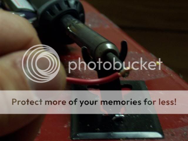
soldering-
hot iron, touch the workpiece to the iron, apply solder to the gap between the iron and the work piece. and then touch the other side of the workpiece with the solder. Quickly cool.
note- use the least ammount of time possible while heating LEDs. It is best to use a metal heat sink of some type to cool the LED. You can only get them so hot for so long before they bust.
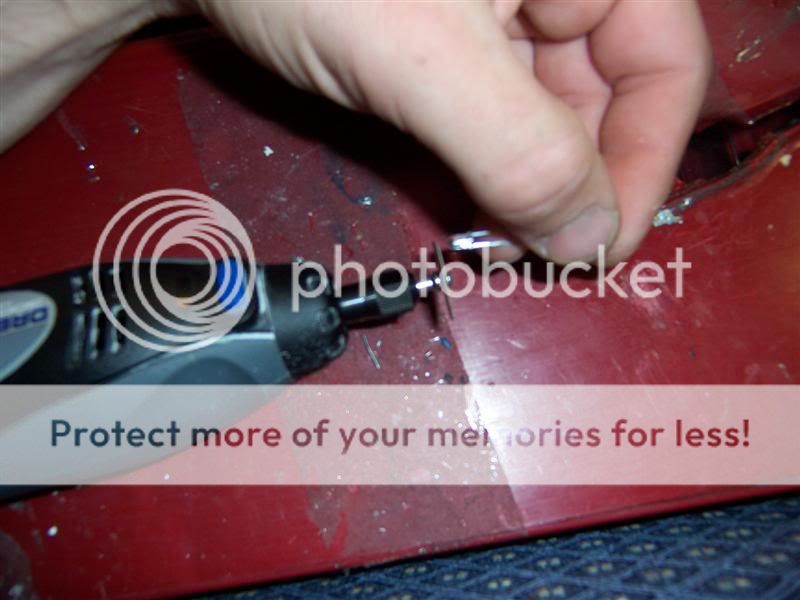
Shave down your LEDs to the minimum size you can. leave a small portion of plastic still covering the cup. don't go too far or you'll render the LED useless. When complete, test the LEDs using a 3V button cell battery from walmart. It would suck for you to try to put them in and have one bad one because it was vibrated too hard, sanded too hot, or sanded too small.
<span style="font-size:12pt;line-height:100%">To get the heater controls out - </span>Installation is the reverse of removal
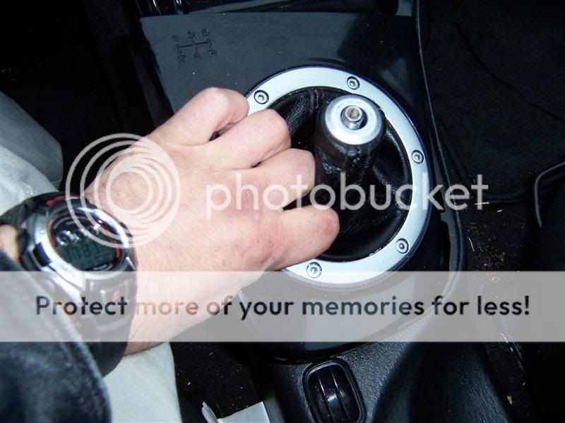
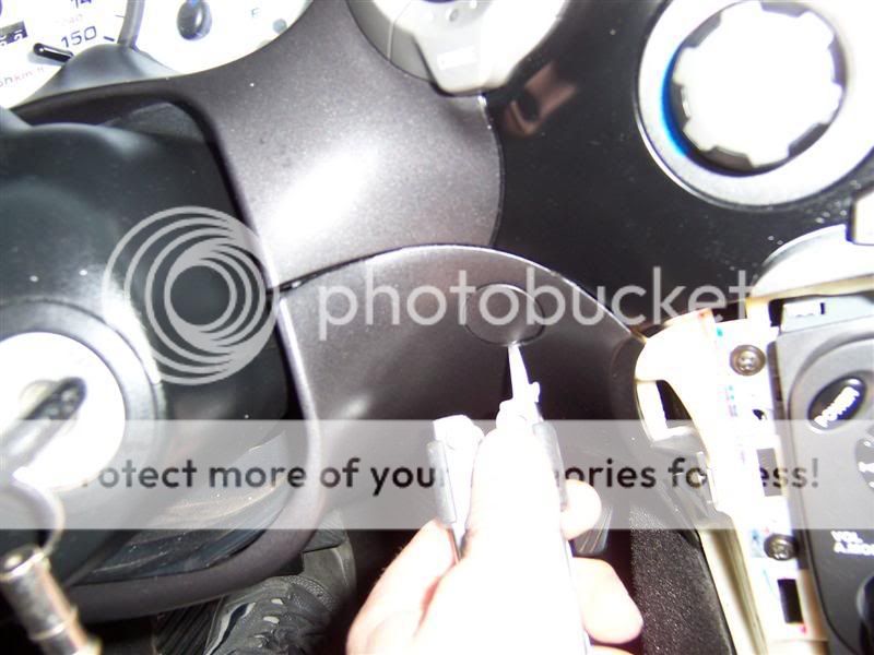
1. remove shifter ball (manual only)
2. pull to remove shifter surround
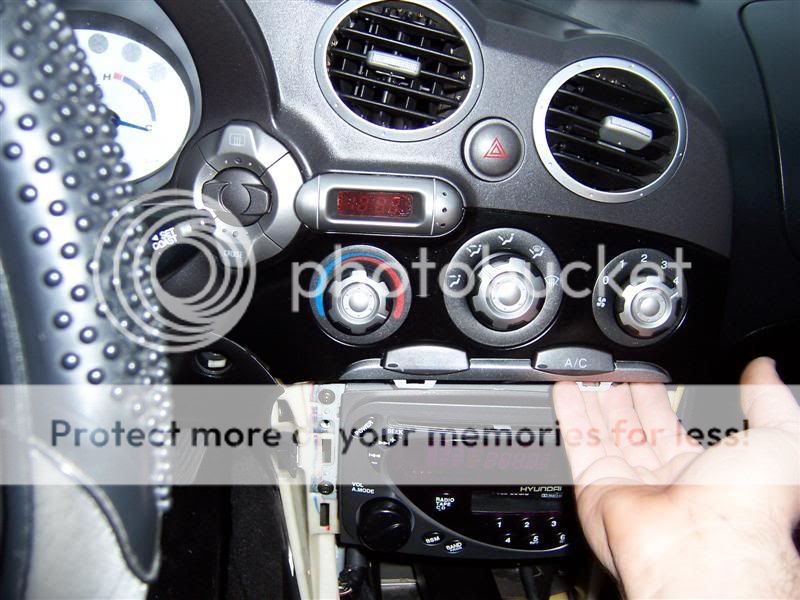
3. pull to remove sterio surround
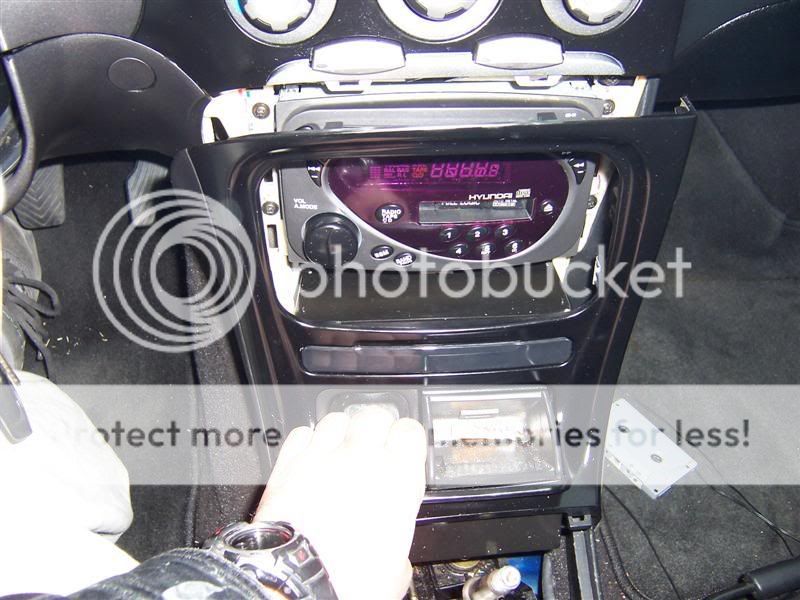
and disconnect jack from plug
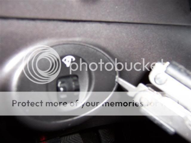
4. pry to remove dimmer switch with a small flat screw driver
5. remove 5 screws one on each corner and one on side securing bottom dash panel with OBD port and hood release
6. remove 6 screws securing dashboard to crash pad- 2 above steering wheel, 2 above radio, and 1 on each side of the steering wheel
Note: at this point it is best to resecure the bottom panel loosely so that you can still sit and work. It puts less stress on cables and keeps it off of your feet. Leave enough gap so that the upper panel will slide out, but the lower panel will be secure.
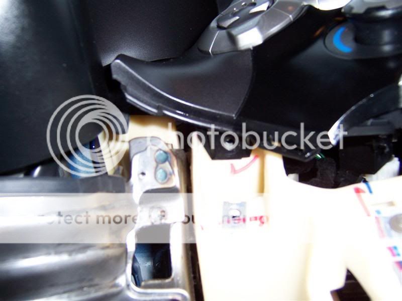
7. remove heater cable link by gas pedal
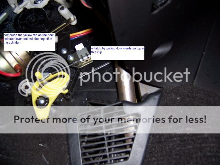
8. pull to pop dashboard from crashpad
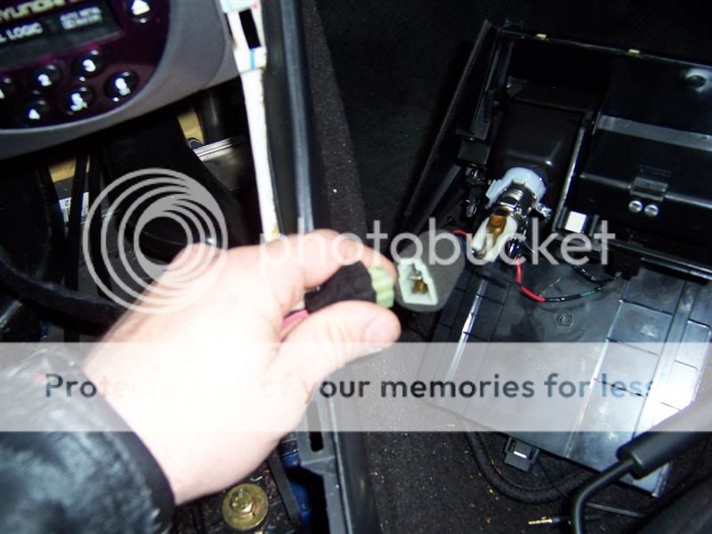
9. disconnect all wire and pneumatic hose connections from dashboard and jacks inside crashpad
10. remove dashboard
11. remove 5 screws securing heater cluster to dashboard
12. remove 3 screws securing switches to dashboard
Skill level: moderate/advanced
You will need:
flat mat clear stensil material (from wallmart)
scissors
sharpie marker
super glue
LEDs and resistors, enough to mess up a few of them.
22AWG wire or larger (diameter)
clear rubber cement
white-out
Dremmel or drill and sand paper
3V button cell battery
soldering iron
solder
desoldering wick or desoldering bulb
smal flat jewelers screw driver
philips screw driver
heat sink
plyers
wire cutters
<span style="font-size:12pt;line-height:100%">Prep work - </span><span style="font-size:10pt;line-height:100%">get what you can done before you remove parts from your vehical
</span>
WIRE-
cut 6 10" strands of wire, 20awg or larger size and tin one end
LEDs-
Make 7 - 10 of these for bulb replacement in switches and center post illumination in heater dials
soldering-
hot iron, touch the workpiece to the iron, apply solder to the gap between the iron and the work piece. and then touch the other side of the workpiece with the solder. Quickly cool.
note- use the least ammount of time possible while heating LEDs. It is best to use a metal heat sink of some type to cool the LED. You can only get them so hot for so long before they bust.
Shave down your LEDs to the minimum size you can. leave a small portion of plastic still covering the cup. don't go too far or you'll render the LED useless. When complete, test the LEDs using a 3V button cell battery from walmart. It would suck for you to try to put them in and have one bad one because it was vibrated too hard, sanded too hot, or sanded too small.
<span style="font-size:12pt;line-height:100%">To get the heater controls out - </span>Installation is the reverse of removal
1. remove shifter ball (manual only)
2. pull to remove shifter surround
3. pull to remove sterio surround
and disconnect jack from plug
4. pry to remove dimmer switch with a small flat screw driver
5. remove 5 screws one on each corner and one on side securing bottom dash panel with OBD port and hood release
6. remove 6 screws securing dashboard to crash pad- 2 above steering wheel, 2 above radio, and 1 on each side of the steering wheel
Note: at this point it is best to resecure the bottom panel loosely so that you can still sit and work. It puts less stress on cables and keeps it off of your feet. Leave enough gap so that the upper panel will slide out, but the lower panel will be secure.
7. remove heater cable link by gas pedal
8. pull to pop dashboard from crashpad
9. disconnect all wire and pneumatic hose connections from dashboard and jacks inside crashpad
10. remove dashboard
11. remove 5 screws securing heater cluster to dashboard
12. remove 3 screws securing switches to dashboard
 02-19-2006, 06:10 PM
#2
Moderator
Thread Starter
<span style="font-size:18pt;line-height:100%">Taking apart the heater cluster
</span>
<u>NOTE: Do not attempt this if you have never tried an electronics upgrade/modification before. This is not a simple procedure and you could really screw something up. You must be able to trust your electronics and soldering ability or risk a fire in your dashboard. There are people on this site including myself who will do it for nearly what you'd pay in parts and shipping.</u>
----CAREFULLY----
1. start by prying at the bottom portion of the switch cap with a flat screw driver
Note: Have superglue ready. If you damage the center portion, it will shine light through. and illumate the switch on light when you turn your illumination on.
2. stick the screw driver through and attempt to work the switch cap out of place with a flat screw driver
3. lift the corner tab slightly with a flat screw driver and remove the wire attached to the switch box.
4. lift the tab securing the switch to the heater with a flat screw driver and slide the switch out of place
5. Do the same thing with the other switch.
<span style="font-size:12pt;line-height:100%">Taking apart cruise/defrost switches
</span>1. remove faces from switches by prying slightly at the tabs holding the caps in place
2. compress tabs and slide out of place
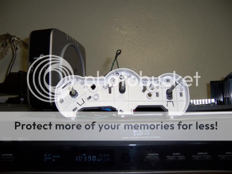
<span style="font-size:12pt;line-height:100%">LEDs in heater console
</span>1. with a screw driver carefully remove faces from switches, and slide out, then unlatch plastic parts holding heater white portion to black portion
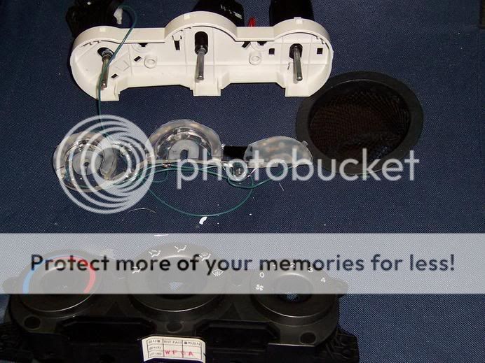
There are two methods to use. The first uses the lense in the center, the seccond does not
<span style="font-size:14pt;line-height:100%">METHOD 1:
</span>2. using a dremmel, mark and drill holes in the lens where you want your LEDs.
note: on the slide heat/cool selection knob, you should put more leds towards the larger portions and less towards the smaler portions.
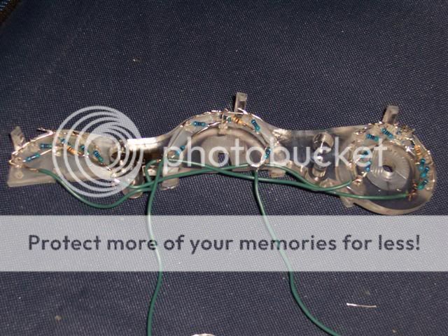
3. clear cement stensil material to the front of the lens to make light distribute more evenly
4. cement leds in place.
5. add resistors and connect all connections in paralell
6. add 1 more LED and resistor for each of the knobs (the more the better)
6. verify that all LEDs will work when hooked up to your vehical for a period of 10 minutes
7. use whiteout to keep the light bouncing where you want it to go.
Note:Cover the lense and leds with whiteout. Do not cover the raised portions of the lense or the guides to keep it in the heater.
8. wiretap, or quick disconnect wires for future removal if desired
<span style="font-size:14pt;line-height:100%">METHOD 2:
</span>
2. Discard the lens into the nearest waste depository.
3. Drill holes at predetermined angles to make light shine onto each indicator in any way possible
4. superglue, epoxy, clear cement LEDs in place in any way you can.
note: you will need a drill to remove LEDs if they go out from overheating or vibration.
5. connect resistors, use a 470 ohm series setup to minimize current flow and lower total wattage
6. test at battery voltage
7. coat with liquid electrical tape
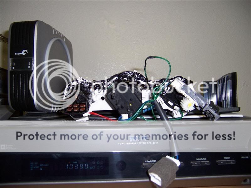
Note: Ugly on the rear, but takes less time then using shrink wrap or wire taps and adds firmness to the project.
Note: Before using liquid electrical tape, make DAMN sure that all connections are exactally as they should be and that you can trust your electronics/soldering ability.
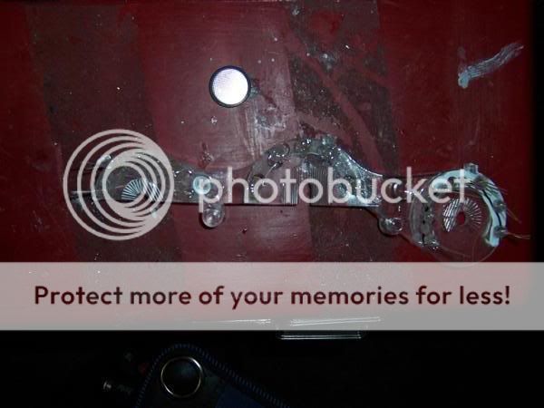
<span style="font-size:18pt;line-height:100%">LEDs in switches from tibby01's origonal post in DIY To Put Leds In Switches</span>
-DTN- Replace stock LEDs with standard LEDs. Ensure that the annode and cathode are pointing the same way. You can check this by looking in the LED to verify which side is the larger of the two and line them up as such. Do not reverse a LED or it will not work.
-DTN- NOTE: Hyundai uses highly toxic chemicals in thier solder for electronics. Use proper ventalation or work outdoors when desoldering or soldering on a hyundai circuit board. Failure to do so will lead to severe headache and probly lots of other things DrivingTibNaked will experience in future life
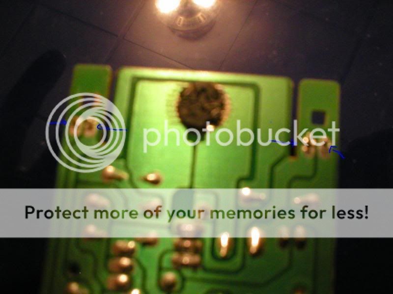
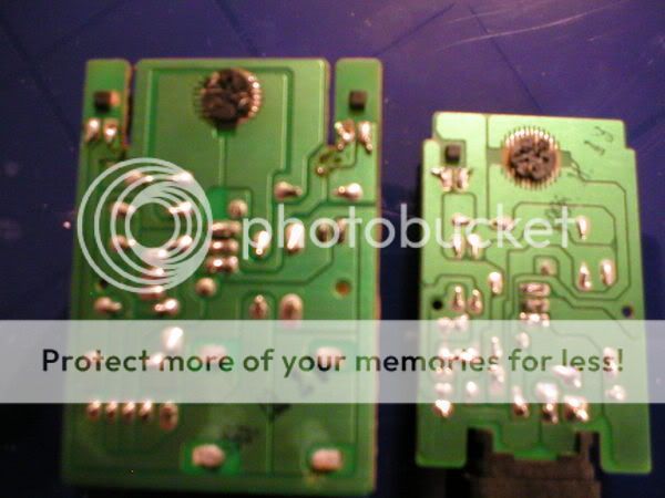

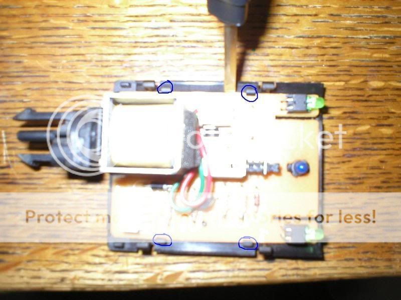
FOR RD1
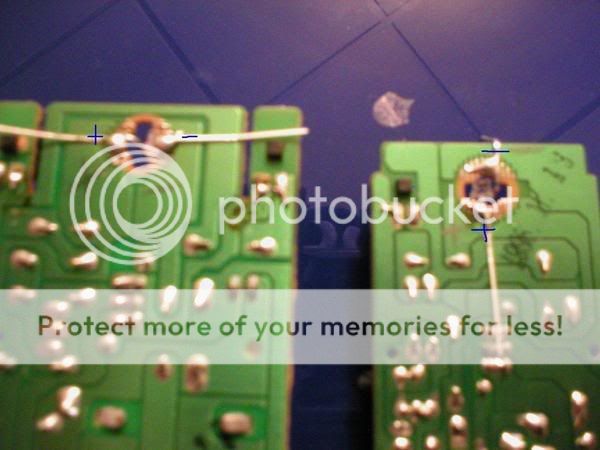
the last one is what you really want to pay attention to. it shows which spots are positive and negative. then you can:
a: cut the circuit <span style="color:#ff0000">in</span> the breadboard on the back and join it back with a resistor soldered across the gap
b: simply cut the illumination wire running to the switch and join it back together with a 470ohm resistor
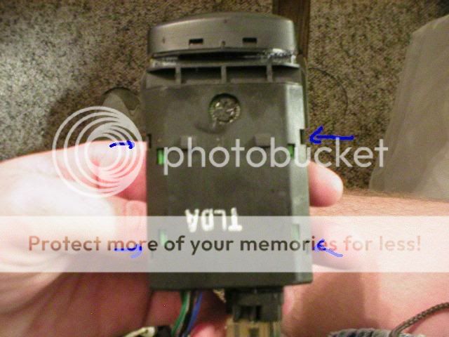
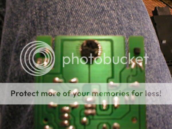
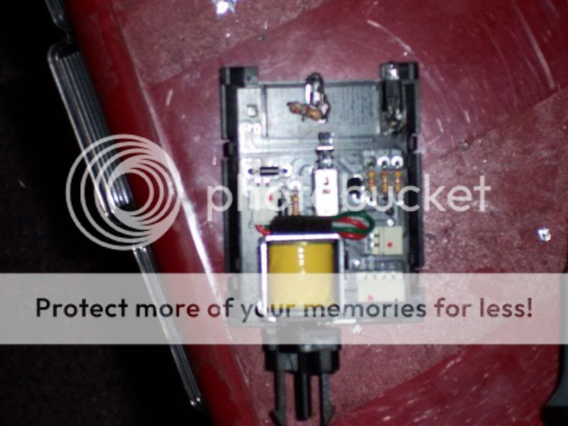
for the cruise, fog, and rear defrost, check this iage out. ind you this is from my crappy memory, so you ight have to switch the led around after putting it <span style="color:#ff0000">in</span>.
rear defrost and fog switch is like this. the cruise switch actually has the + and - switched( i think)
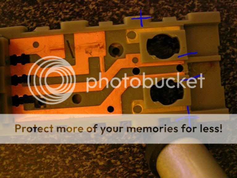
then for the resistor, i cut the circuit where you see the black lines, then i rejoin it with a resistor.
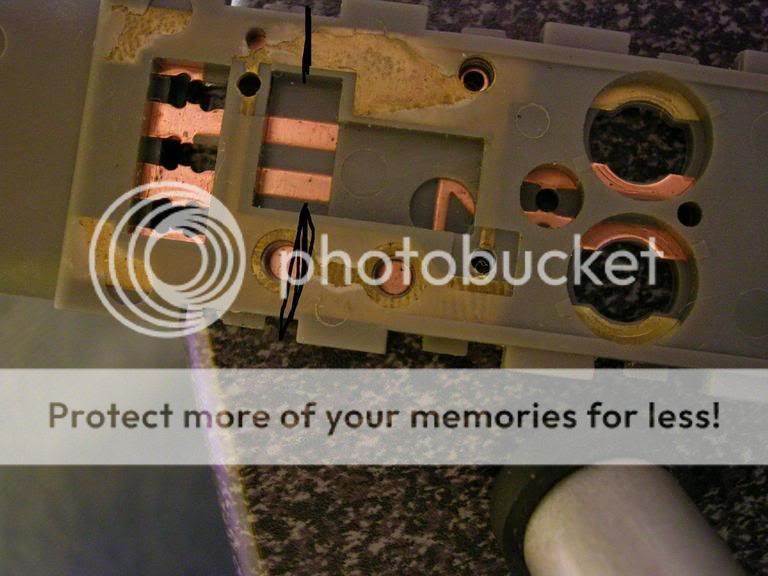
hope that helps. any quesitons just ask.
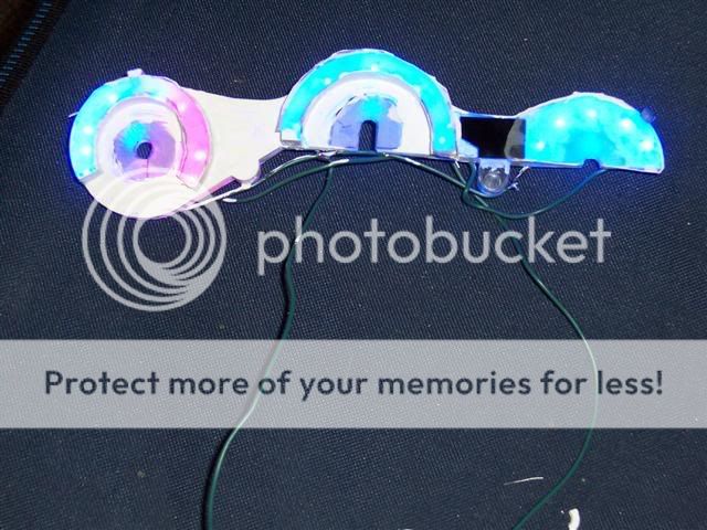
<span style="font-size:18pt;line-height:100%">Should look like this when done.</span>
dim:

bright, and blury, sorry. you can't tell very well because resize ruined my picture, but the lights vary greatly in intensity. The controls are actually VERY even, the camera discolors the pictures at night because of the glare.

Total project time: 10-12 hours
Link to DIY on putting a LED into the dimmer switch.
http://www.rdtiburon.com/index.php?showtop...mp;gopid=264606
</span>
<u>NOTE: Do not attempt this if you have never tried an electronics upgrade/modification before. This is not a simple procedure and you could really screw something up. You must be able to trust your electronics and soldering ability or risk a fire in your dashboard. There are people on this site including myself who will do it for nearly what you'd pay in parts and shipping.</u>
----CAREFULLY----
1. start by prying at the bottom portion of the switch cap with a flat screw driver
Note: Have superglue ready. If you damage the center portion, it will shine light through. and illumate the switch on light when you turn your illumination on.
2. stick the screw driver through and attempt to work the switch cap out of place with a flat screw driver
3. lift the corner tab slightly with a flat screw driver and remove the wire attached to the switch box.
4. lift the tab securing the switch to the heater with a flat screw driver and slide the switch out of place
5. Do the same thing with the other switch.
<span style="font-size:12pt;line-height:100%">Taking apart cruise/defrost switches
</span>1. remove faces from switches by prying slightly at the tabs holding the caps in place
2. compress tabs and slide out of place
<span style="font-size:12pt;line-height:100%">LEDs in heater console
</span>1. with a screw driver carefully remove faces from switches, and slide out, then unlatch plastic parts holding heater white portion to black portion
There are two methods to use. The first uses the lense in the center, the seccond does not
<span style="font-size:14pt;line-height:100%">METHOD 1:
</span>2. using a dremmel, mark and drill holes in the lens where you want your LEDs.
note: on the slide heat/cool selection knob, you should put more leds towards the larger portions and less towards the smaler portions.
3. clear cement stensil material to the front of the lens to make light distribute more evenly
4. cement leds in place.
5. add resistors and connect all connections in paralell
6. add 1 more LED and resistor for each of the knobs (the more the better)
6. verify that all LEDs will work when hooked up to your vehical for a period of 10 minutes
7. use whiteout to keep the light bouncing where you want it to go.
Note:Cover the lense and leds with whiteout. Do not cover the raised portions of the lense or the guides to keep it in the heater.
8. wiretap, or quick disconnect wires for future removal if desired
<span style="font-size:14pt;line-height:100%">METHOD 2:
</span>
2. Discard the lens into the nearest waste depository.
3. Drill holes at predetermined angles to make light shine onto each indicator in any way possible
4. superglue, epoxy, clear cement LEDs in place in any way you can.
note: you will need a drill to remove LEDs if they go out from overheating or vibration.
5. connect resistors, use a 470 ohm series setup to minimize current flow and lower total wattage
6. test at battery voltage
7. coat with liquid electrical tape
Note: Ugly on the rear, but takes less time then using shrink wrap or wire taps and adds firmness to the project.
Note: Before using liquid electrical tape, make DAMN sure that all connections are exactally as they should be and that you can trust your electronics/soldering ability.
<span style="font-size:18pt;line-height:100%">LEDs in switches from tibby01's origonal post in DIY To Put Leds In Switches</span>
-DTN- Replace stock LEDs with standard LEDs. Ensure that the annode and cathode are pointing the same way. You can check this by looking in the LED to verify which side is the larger of the two and line them up as such. Do not reverse a LED or it will not work.
-DTN- NOTE: Hyundai uses highly toxic chemicals in thier solder for electronics. Use proper ventalation or work outdoors when desoldering or soldering on a hyundai circuit board. Failure to do so will lead to severe headache and probly lots of other things DrivingTibNaked will experience in future life
FOR RD1
the last one is what you really want to pay attention to. it shows which spots are positive and negative. then you can:
a: cut the circuit <span style="color:#ff0000">in</span> the breadboard on the back and join it back with a resistor soldered across the gap
b: simply cut the illumination wire running to the switch and join it back together with a 470ohm resistor
for the cruise, fog, and rear defrost, check this iage out. ind you this is from my crappy memory, so you ight have to switch the led around after putting it <span style="color:#ff0000">in</span>.
rear defrost and fog switch is like this. the cruise switch actually has the + and - switched( i think)
then for the resistor, i cut the circuit where you see the black lines, then i rejoin it with a resistor.
hope that helps. any quesitons just ask.
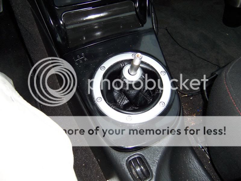
<span style="font-size:18pt;line-height:100%">Should look like this when done.</span>
dim:
bright, and blury, sorry. you can't tell very well because resize ruined my picture, but the lights vary greatly in intensity. The controls are actually VERY even, the camera discolors the pictures at night because of the glare.
Total project time: 10-12 hours
Link to DIY on putting a LED into the dimmer switch.
http://www.rdtiburon.com/index.php?showtop...mp;gopid=264606
 02-20-2006, 12:53 AM
#4
Moderator
Thread Starter
It's one way of doing it, and it seems the cleanest. I'll be adding the other method as well as pics of dashboard removal and a few others.
02-21-2006, 10:08 AM
#5
Senior Member
Join Date: Mar 2002
Location: Los Lunas, New Mexico, USA.
Posts: 34,642
Likes: 0
Received 0 Likes
on
0 Posts
Vehicle: 2001 Hyundai Tiburon, 2004 Kia Sorento, 2010 Kia Soul
Wow, that came out really nice and clean. It'd be nice to see some more pics of the dissasembly of the actual AC control module.
Tibby01, you payin attention here?!? LOL
Tibby01, you payin attention here?!? LOL
02-21-2006, 11:27 AM
#6
Moderator
Thread Starter
got an error: Sorry, but you have posted more images than you are allowed to
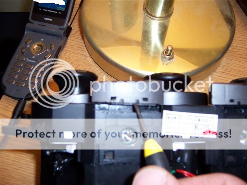
<span style="font-size:12pt;line-height:100%">removing switches from heater-
</span>
----CAREFULLY----
1. start by prying at the bottom portion of the switch cap with a flat screw driver
Note: Have superglue ready. If you damage the center portion, it will shine light through. and illumate the switch on light when you turn your illumination on.
2. stick the screw driver through and attempt to work the switch cap out of place with a flat screw driver
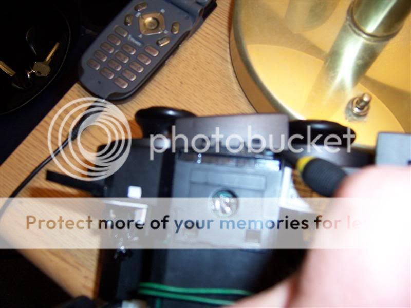
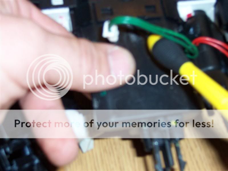
3. lift the corner tab slightly with a flat screw driver and remove the wire attached to the switch box.
4. lift the tab securing the switch to the heater with a flat screw driver and slide the switch out of place
5. Do the same thing with the other switch.
<span style="font-size:12pt;line-height:100%">removing switches from heater-
</span>
----CAREFULLY----
1. start by prying at the bottom portion of the switch cap with a flat screw driver
Note: Have superglue ready. If you damage the center portion, it will shine light through. and illumate the switch on light when you turn your illumination on.
2. stick the screw driver through and attempt to work the switch cap out of place with a flat screw driver
3. lift the corner tab slightly with a flat screw driver and remove the wire attached to the switch box.
4. lift the tab securing the switch to the heater with a flat screw driver and slide the switch out of place
5. Do the same thing with the other switch.
02-22-2006, 02:09 PM
#7
Senior Member

Join Date: Mar 2006
Posts: 537
Likes: 0
Received 0 Likes
on
0 Posts
Vehicle: 1998 Hyundai Tiburon
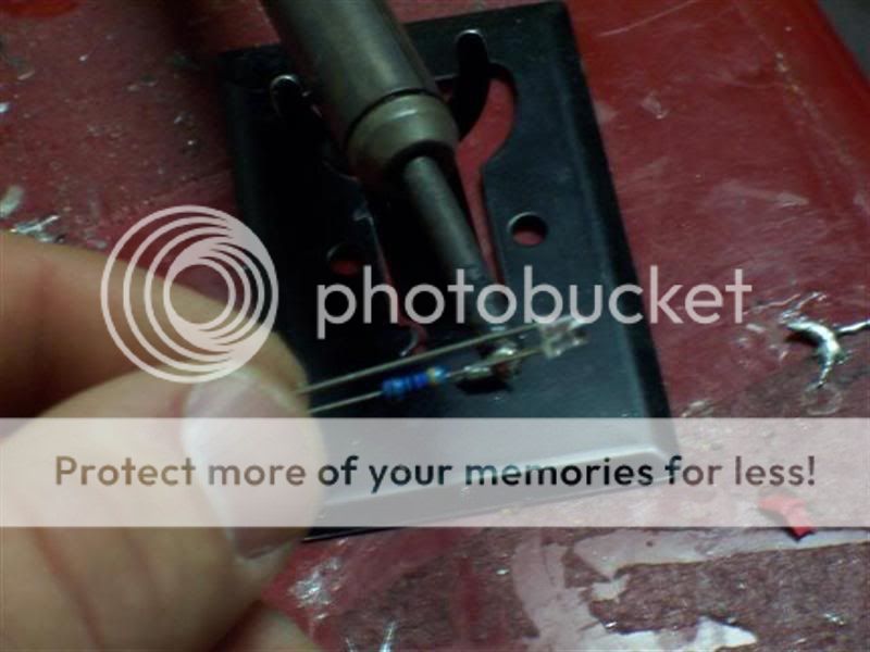
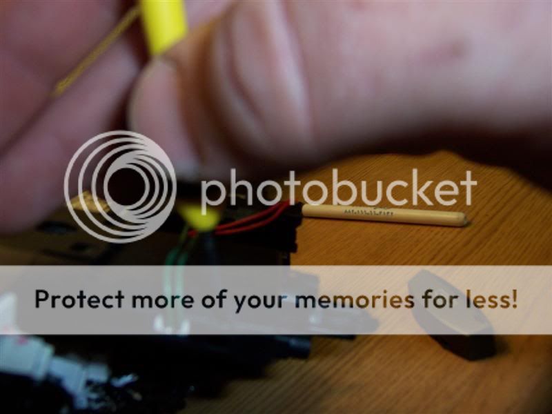
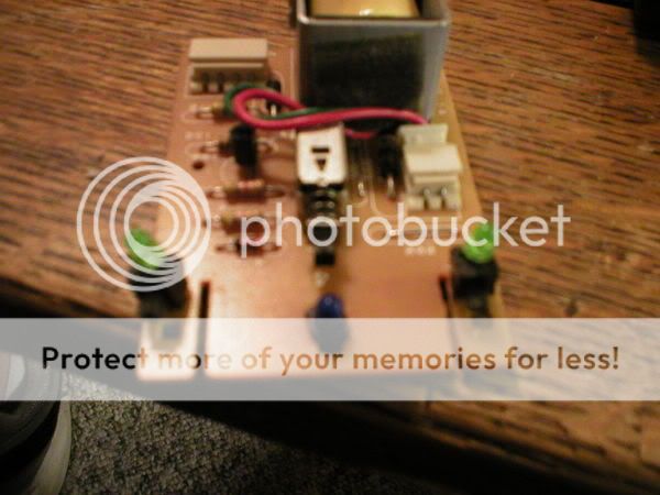
I've got a couple questions for you. What kind of material is that you're using to distribute the light? How do you have the LED's wired? In series right, how does that work? I've seen them wired like that, but have never done it. And, what is the brown colored resistor in there for?
02-22-2006, 03:00 PM
#8
Moderator
Thread Starter
stensil material is used to distribute light. you need to find something transparent with texture. Stensils from walmart will do the job.
It is very much more power conserving to use a 470 ohm resistor and 2 LEDs in series, but with the size of the work piece, it is difficult to do. Using some 560ohm resistors and running them all in paralell works, but uses more power. about 5 watts instead of 2 watts. it's still a small ammount of wattage.
there is one resistor that is different colored because it came from a different batch. i made a bunch of what i call "560 shorts" for placing 1 led somewhere. 560 denotes resistance value and the short denotes that the legs have been chopped and a resistor has been placed on them.. makes it easier for labling purposes when searching for an item. ALL leds should be shaved to distribute light better.
02-22-2006, 05:23 PM
#10
Moderator
Thread Starter
for 470s you'll have to run a set of 2 in series per resistor. it will be a bit more difficult to manage because of that, but it's possible. I perfer to just keep it simpler. it takes alot of thought to run a bunch of series-paralell circuits.
if you use 470s in paralell, you'll be overdriving the LEDs to about 22mA instead of their recommended 20mA. this will decrease life and increase heat output which in turn also decreases life.
You may want to fork out the extra few bux and go to radio shack to get a 100 ohm 10W wire-wound block resistor. you can put it in the deadspace at the bottom of the heater cluster they're about 1/2" by 1/2: by 2" long. they're pretty big, but they fit inside the heater controls...
as for the switches backlighting... you can try to do some creative rewiring on them, pick up a few 560s at radioshack, or you can just overdrive those 2 LEDs.